
1. 簡介

Nest 發布的 OpenThread 是 Thread® 網路通訊協定的開放原始碼實作。Nest 已發布 OpenThread,開放開發人員廣泛使用 Nest 產品中的技術,加快智慧聯網家庭產品的開發速度。
Thread 規格定義了適用於家用應用程式的 IPv6 型可靠、安全低功率無線裝置對裝置通訊協定。OpenThread 實作所有 Thread 網路層,包括 IPv6、6LoWPAN、IEEE 802.15.4,以及 MAC 安全性、網狀連結建立和網格轉送。
在本程式碼研究室中,您將使用 OpenThread API 啟動 Thread 網路、監控裝置角色異動並做出回應、傳送 UDP 訊息,以及將這些動作連結至實體硬體上的按鈕和 LED 燈。
課程內容
- 如何在 Nordic nRF52840 開發板上設計按鈕和 LED 燈
- 如何使用常見的 OpenThread API 和
otInstance類別 - 如何監控及回應 OpenThread 狀態變更
- 如何將 UDP 訊息傳送至 Thread 網路中的所有裝置
- 如何修改 Makefiles
軟硬體需求
硬體:
- 3 北歐半導體 nRF52840 開發板
- 使用 3 條 USB 轉 Micro-USB 傳輸線連接鍵盤
- 擁有至少 3 個 USB 連接埠的 Linux 電腦
軟體:
- GNU 工具鍊
- Nordic nRF5x 指令列工具
- Sgger J-Link 軟體
- OpenThread
- Git
除非另有註明,否則本程式碼研究室的內容是採用創用 CC 姓名標示 3.0 授權,程式碼範例則採用阿帕契 2.0 授權。
2. 開始使用
完成硬體程式碼研究室
開始這個程式碼研究室之前,您應該先完成使用 nRF52840 董事會和 OpenThread 建構 Thread 網路程式碼研究室,其中包含:
- 詳細說明建構及刷新作業所需的所有軟體
- 說明如何建構 OpenThread 並在 Nordic nRF52840 主機板上刷新
- 示範 Thread 網路的基本概念
本程式碼研究室只介紹了刷新板的基本操作說明,建構 OpenThread 和刷新板時,所有環境都不需要設定。我們假設您已完成「Build a Thread 網路」程式碼研究室。
Linux 機器
本程式碼研究室旨在使用 i386 或 x86 型 Linux 機器刷新所有 Thread 開發板。所有步驟皆已在 Ubuntu 14.04.5 LTS (Trusty Tahr) 上測試。
北歐半導體 nRF52840 主機
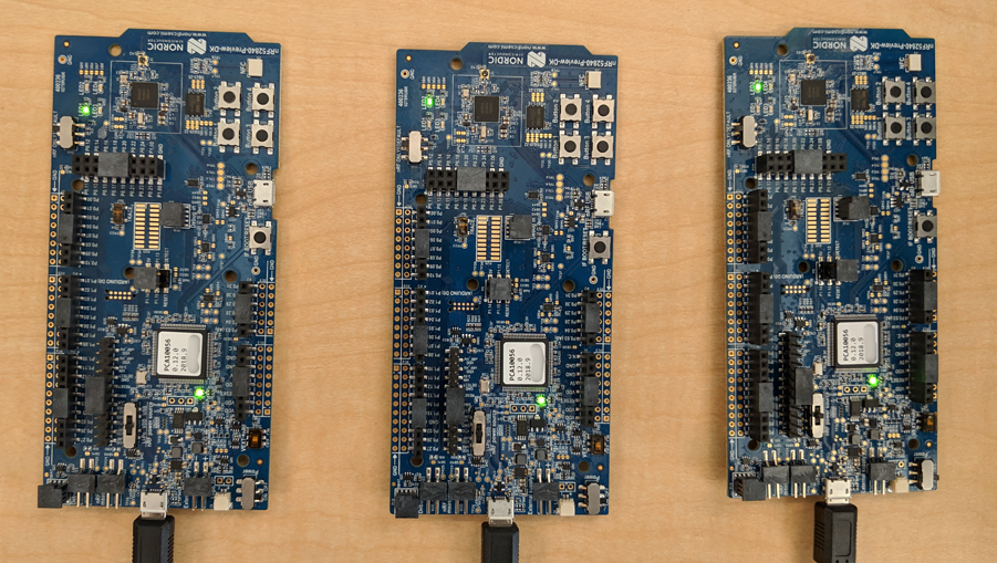
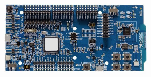
本程式碼研究室採用三個 nRF52840 PDK 主機板。
安裝軟體
如要建構及刷新 OpenThread,您必須安裝 SEGGER J-Link、nRF5x 指令列工具、ARM GNU 工具鍊和各種 Linux 套件。如果您已按照需求完成「Build a Thread 網路程式碼研究室」課程,則已安裝所有必要元件。如果沒有,請先完成程式碼研究室再繼續操作,確保您可以建構 OpenThread 並刷新至 nRF52840 開發板。
3. 複製存放區
OpenThread 提供範例應用程式,可做為本程式碼研究室的起點。
複製 OpenThread Nordic nRF528xx 範例存放區並建構 OpenThread:
$ git clone --recursive https://github.com/openthread/ot-nrf528xx
$ cd ot-nrf528xx
$ ./script/bootstrap
4. OpenThread API 基本概念
OpenThread 的公開 API 位於 OpenThread 存放區的 ./openthread/include/openthread 中。這些 API 可在 Thread 和平台層級存取多種 OpenThread 功能,方便您在應用程式中使用:
- OpenThread 執行個體資訊與控制選項
- IPv6、UDP 和 CoAP 等應用程式服務
- 網路憑證管理,以及「佣金」和「彙整者」角色
- 邊界路由器管理
- 進階功能,例如兒童監督和 Jam 偵測
如要查看所有 OpenThread API 的參考資料,請前往 openthread.io/reference。
使用 API
如要使用 API,請在其中一個應用程式檔案中加入其標頭檔案。然後呼叫所需函式。
舉例來說,OpenThread 內含的 CLI 範例應用程式會使用下列 API 標頭:
./openthread/examples/apps/cli/main.c
#include <openthread/config.h>
#include <openthread/cli.h>
#include <openthread/diag.h>
#include <openthread/tasklet.h>
#include <openthread/platform/logging.h>
OpenThread 執行個體
otInstance 結構是您在使用 OpenThread API 時會經常使用的結構。初始化後,這個結構代表 OpenThread 程式庫的靜態執行個體,並允許使用者發出 OpenThread API 呼叫。
舉例來說,OpenThread 執行個體是透過 CLI 範例應用程式的 main() 函式初始化:
./openthread/examples/apps/cli/main.c
int main(int argc, char *argv[])
{
    otInstance *instance

...

#if OPENTHREAD_ENABLE_MULTIPLE_INSTANCES
    // Call to query the buffer size
    (void)otInstanceInit(NULL, &otInstanceBufferLength);

    // Call to allocate the buffer
    otInstanceBuffer = (uint8_t *)malloc(otInstanceBufferLength);
    assert(otInstanceBuffer);

    // Initialize OpenThread with the buffer
    instance = otInstanceInit(otInstanceBuffer, &otInstanceBufferLength);
#else
    instance = otInstanceInitSingle();
#endif

...

    return 0;
}
平台專屬函式
如要將平台專屬函式加入 OpenThread 包含的其中一個範例應用程式,請先在 ./openthread/examples/platforms/openthread-system.h 標頭中宣告這些函式,並針對所有函式使用 otSys 命名空間。然後在平台專屬的來源檔案中實作。所幸,您可以使用在其他範例平台的同一個函式標頭。
例如,我們將要使用的 GPIO 函式連接至 nRF52840 按鈕,而 LED 必須在 openthread-system.h 中宣告。
使用您偏好的文字編輯器開啟 ./openthread/examples/platforms/openthread-system.h 檔案。
./openthread/examples/platforms/openthread-system.h
動作:新增平台專屬的 GPIO 函式宣告。
請在 openthread/instance.h 標頭的 #include 後方加上以下函式宣告:
/**
 * Init LED module.
 *
 */
void otSysLedInit(void);
void otSysLedSet(uint8_t aLed, bool aOn);
void otSysLedToggle(uint8_t aLed);

/**
* A callback will be called when GPIO interrupts occur.
*
*/
typedef void (*otSysButtonCallback)(otInstance *aInstance);
void otSysButtonInit(otSysButtonCallback aCallback);
void otSysButtonProcess(otInstance *aInstance);
我們將在下一個步驟中導入這些功能。
請注意,otSysButtonProcess 函式宣告使用 otInstance。這樣一來,在使用者按下按鈕時,應用程式就能存取 OpenThread 執行個體的相關資訊 (如有需要)。這都取決於應用程式的需求。如果實作函式時不需要這個巨集,您可以使用 OpenThread API 中的 OT_UNUSED_VARIABLE 巨集,針對部分工具鍊中未使用的變數隱藏建構錯誤。我們稍後會舉例說明。
5. 實作 GPIO 平台抽象層
在上一個步驟中,我們探討了可用於 GPIO 的平台專屬函式宣告./openthread/examples/platforms/openthread-system.h。如要使用 nRF52840 開發板上的按鈕和 LED 燈,您必須針對 nRF52840 平台實作這些功能。在這個程式碼中,您將新增函式:
- 初始化 GPIO 接腳和模式
- 控制針腳的電壓
- 啟用 GPIO 中斷並註冊回呼
在 ./src/src 目錄中,建立名為 gpio.c 的新檔案。在這個新檔案中,加入以下內容。
./src/src/gpio.c (新檔案)
動作:新增定義。
這些定義的用途是 nRF52840 特定值與在 OpenThread 應用程式層級中使用的變數之間的抽象層。
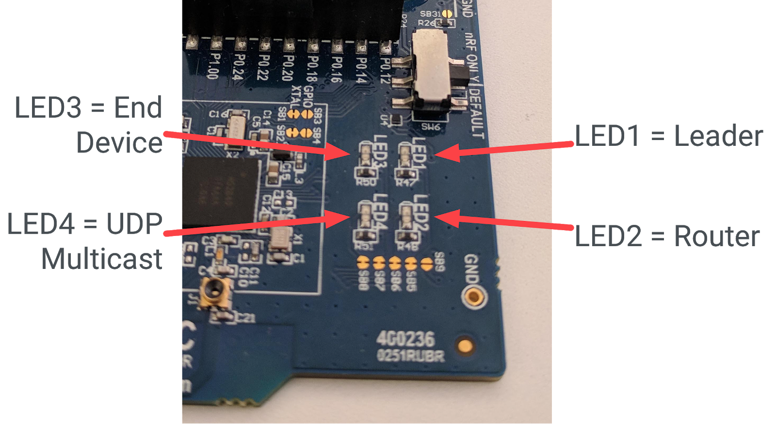
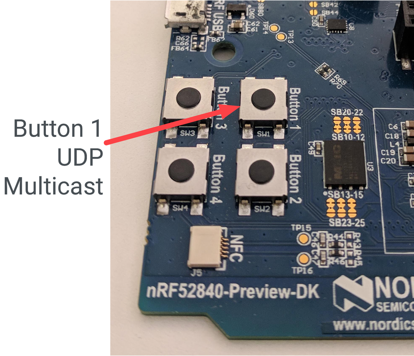
/**
 * @file
 *   This file implements the system abstraction for GPIO and GPIOTE.
 *
 */

#define BUTTON_GPIO_PORT 0x50000300UL
#define BUTTON_PIN 11 // button #1

#define GPIO_LOGIC_HI 0
#define GPIO_LOGIC_LOW 1

#define LED_GPIO_PORT 0x50000300UL
#define LED_1_PIN 13 // turn on to indicate leader role
#define LED_2_PIN 14 // turn on to indicate router role
#define LED_3_PIN 15 // turn on to indicate child role
#define LED_4_PIN 16 // turn on to indicate UDP receive
如要進一步瞭解 nRF52840 按鈕和 LED 燈,請參閱北半導體資訊中心。
動作:新增標頭包含項目。
接下來,新增標頭包括 GPIO 功能所需的資訊。
/* Header for the functions defined here */
#include "openthread-system.h"

#include <string.h>

/* Header to access an OpenThread instance */
#include <openthread/instance.h>

/* Headers for lower-level nRF52840 functions */
#include "platform-nrf5.h"
#include "hal/nrf_gpio.h"
#include "hal/nrf_gpiote.h"
#include "nrfx/drivers/include/nrfx_gpiote.h"
動作:新增按鈕 1 的回呼和中斷函式。
接著再新增此程式碼。in_pin1_handler 函式是按下按鈕功能初始化時 (這個檔案的後續章節) 註冊的回呼。
請注意此回呼如何使用 OT_UNUSED_VARIABLE 巨集,因為函式實際上並未使用傳遞至 in_pin1_handler 的變數。
/* Declaring callback function for button 1. */
static otSysButtonCallback sButtonHandler;
static bool                sButtonPressed;

/**
 * @brief Function to receive interrupt and call back function
 * set by the application for button 1.
 *
 */
static void in_pin1_handler(uint32_t pin, nrf_gpiote_polarity_t action)
{
    OT_UNUSED_VARIABLE(pin);
    OT_UNUSED_VARIABLE(action);
    sButtonPressed = true;
}
動作:新增用來設定 LED 的函式。
加入這個程式碼即可設定初始化期間所有 LED 的模式和狀態。
/**
 * @brief Function for configuring: PIN_IN pin for input, PIN_OUT pin for output,
 * and configures GPIOTE to give an interrupt on pin change.
 */

void otSysLedInit(void)
{
    /* Configure GPIO mode: output */
    nrf_gpio_cfg_output(LED_1_PIN);
    nrf_gpio_cfg_output(LED_2_PIN);
    nrf_gpio_cfg_output(LED_3_PIN);
    nrf_gpio_cfg_output(LED_4_PIN);

    /* Clear all output first */
    nrf_gpio_pin_write(LED_1_PIN, GPIO_LOGIC_LOW);
    nrf_gpio_pin_write(LED_2_PIN, GPIO_LOGIC_LOW);
    nrf_gpio_pin_write(LED_3_PIN, GPIO_LOGIC_LOW);
    nrf_gpio_pin_write(LED_4_PIN, GPIO_LOGIC_LOW);

    /* Initialize gpiote for button(s) input.
     Button event handlers are set in the application (main.c) */
    ret_code_t err_code;
    err_code = nrfx_gpiote_init();
    APP_ERROR_CHECK(err_code);
}
動作:新增用來設定 LED 燈模式的函式。
裝置角色變更時,系統會使用這個函式。
/**
 * @brief Function to set the mode of an LED.
 */

void otSysLedSet(uint8_t aLed, bool aOn)
{
    switch (aLed)
    {
    case 1:
        nrf_gpio_pin_write(LED_1_PIN, (aOn == GPIO_LOGIC_HI));
        break;
    case 2:
        nrf_gpio_pin_write(LED_2_PIN, (aOn == GPIO_LOGIC_HI));
        break;
    case 3:
        nrf_gpio_pin_write(LED_3_PIN, (aOn == GPIO_LOGIC_HI));
        break;
    case 4:
        nrf_gpio_pin_write(LED_4_PIN, (aOn == GPIO_LOGIC_HI));
        break;
    }
}
動作:新增函式來切換 LED 燈模式。
當裝置收到多點傳播 UDP 訊息時,系統會使用這項功能切換 LED4。
/**
 * @brief Function to toggle the mode of an LED.
 */
void otSysLedToggle(uint8_t aLed)
{
    switch (aLed)
    {
    case 1:
        nrf_gpio_pin_toggle(LED_1_PIN);
        break;
    case 2:
        nrf_gpio_pin_toggle(LED_2_PIN);
        break;
    case 3:
        nrf_gpio_pin_toggle(LED_3_PIN);
        break;
    case 4:
        nrf_gpio_pin_toggle(LED_4_PIN);
        break;
    }
}
動作:新增用於初始化及處理按鈕按下動作的函式。
第一個函式會在按下按鈕時初始化 Jamboard,第二個函式則會在按下按鈕 1 時傳送多點傳播 UDP 訊息。
/**
 * @brief Function to initialize the button.
 */
void otSysButtonInit(otSysButtonCallback aCallback)
{
    nrfx_gpiote_in_config_t in_config = NRFX_GPIOTE_CONFIG_IN_SENSE_LOTOHI(true);
    in_config.pull                    = NRF_GPIO_PIN_PULLUP;

    ret_code_t err_code;
    err_code = nrfx_gpiote_in_init(BUTTON_PIN, &in_config, in_pin1_handler);
    APP_ERROR_CHECK(err_code);

    sButtonHandler = aCallback;
    sButtonPressed = false;

    nrfx_gpiote_in_event_enable(BUTTON_PIN, true);
}

void otSysButtonProcess(otInstance *aInstance)
{
    if (sButtonPressed)
    {
        sButtonPressed = false;
        sButtonHandler(aInstance);
    }
}
動作:儲存並關閉 gpio.c 檔案。
6. API:回應裝置角色變更
在應用程式中,我們希望根據裝置角色使用不同的 LED 燈。讓我們追蹤下列角色:領導者、路由器、終端裝置。我們可以按照以下方式為 LED 燈配置:
- LED1 = 領導者
- LED2 = 路由器
- LED 3 = 終端裝置
如要啟用這項功能,應用程式必須知道裝置角色何時變更,以及如何開啟正確的 LED 燈。我們會針對第一個部分使用 OpenThread 執行個體,第二個部分使用 GPIO 平台抽象層。
使用您偏好的文字編輯器開啟 ./openthread/examples/apps/cli/main.c 檔案。
./openthread/examples/apps/cli/main.c
動作:新增標頭包含項目。
在 main.c 檔案的包含部分,新增角色變更功能所需的 API 標頭檔案。
#include <openthread/instance.h>
#include <openthread/thread.h>
#include <openthread/thread_ftd.h>
動作:針對 OpenThread 執行個體狀態變更新增處理常式函式宣告。
將此宣告新增至 main.c,在標頭包含任何 #if 陳述式之後。此函式會在主要應用程式之後定義。
void handleNetifStateChanged(uint32_t aFlags, void *aContext);
動作:新增狀態變更處理常式函式的回呼註冊。
在 main.c 中,於 otAppCliInit 呼叫後方,將此函式新增至 main() 函式。這項回呼註冊作業會指示 OpenThread 在每次 OpenThread 執行個體狀態變更時呼叫 handleNetifStateChange 函式。
/* Register Thread state change handler */
otSetStateChangedCallback(instance, handleNetifStateChanged, instance);
動作:新增狀態變更導入。
在 main.c 中的 main() 函式後方,實作 handleNetifStateChanged 函式。這個函式會檢查 OpenThread 執行個體的 OT_CHANGED_THREAD_ROLE 旗標,如果變更,系統會視需要開啟/關閉 LED。
void handleNetifStateChanged(uint32_t aFlags, void *aContext)
{
   if ((aFlags & OT_CHANGED_THREAD_ROLE) != 0)
   {
       otDeviceRole changedRole = otThreadGetDeviceRole(aContext);

       switch (changedRole)
       {
       case OT_DEVICE_ROLE_LEADER:
           otSysLedSet(1, true);
           otSysLedSet(2, false);
           otSysLedSet(3, false);
           break;

       case OT_DEVICE_ROLE_ROUTER:
           otSysLedSet(1, false);
           otSysLedSet(2, true);
           otSysLedSet(3, false);
           break;

       case OT_DEVICE_ROLE_CHILD:
           otSysLedSet(1, false);
           otSysLedSet(2, false);
           otSysLedSet(3, true);
           break;

       case OT_DEVICE_ROLE_DETACHED:
       case OT_DEVICE_ROLE_DISABLED:
           /* Clear LED4 if Thread is not enabled. */
           otSysLedSet(4, false);
           break;
        }
    }
}
7. API:使用多點傳播技術開啟 LED
在應用程式中,於在單板上按下 Button1 時,我們也想在應用程式中傳送 UDP 訊息到網路中的所有其他裝置。為確認已收到訊息,我們會在其他留言板上切換 LED 4 來回應。
如要啟用這項功能,應用程式必須符合以下條件:
- 啟動時初始化 UDP 連線
- 能傳送 UDP 訊息至網狀本機多點傳播位址
- 處理傳入的 UDP 訊息
- 切換 LED4 以回應收到的 UDP 訊息
使用您偏好的文字編輯器開啟 ./openthread/examples/apps/cli/main.c 檔案。
./openthread/examples/apps/cli/main.c
動作:新增標頭包含項目。
在 main.c 檔案頂端的「包含」部分,新增多點傳播 UDP 功能所需的 API 標頭檔案。
#include <string.h>

#include <openthread/message.h>
#include <openthread/udp.h>

#include "utils/code_utils.h"
code_utils.h 標頭可用於 otEXPECT 和 otEXPECT_ACTION 巨集,以便驗證執行階段條件並妥善處理錯誤。
動作:新增定義和常數:
在 main.c 檔案中,於 include 區段之間和任何 #if 陳述式之後,新增 UDP 專用的常數並定義:
#define UDP_PORT 1212

static const char UDP_DEST_ADDR[] = "ff03::1";
static const char UDP_PAYLOAD[]   = "Hello OpenThread World!";
ff03::1 是網狀本機多點傳播位址。傳送至這個地址的所有訊息都會傳送給該網路中的所有 Full Thread 裝置。如要進一步瞭解 OpenThread 的多點傳播支援,請參閱「openthread.io 的多點傳播」。
動作:新增函式宣告。
在 main.c 檔案的 otTaskletsSignalPending 定義後方和 main() 函式之前,新增 UDP 專屬函式與靜態變數來代表 UDP 通訊端:
static void initUdp(otInstance *aInstance);
static void sendUdp(otInstance *aInstance);

static void handleButtonInterrupt(otInstance *aInstance);

void handleUdpReceive(void *aContext, otMessage *aMessage,
                      const otMessageInfo *aMessageInfo);

static otUdpSocket sUdpSocket;
動作:新增呼叫來初始化 GPIO LED 和按鈕。
在 main.c 中,於 otSetStateChangedCallback 呼叫後方,將這些函式呼叫新增至 main() 函式。這些函式會初始化 GPIO 和 GPIOTE 接腳,並設定用於處理按鈕推送事件的按鈕處理常式。
/* init GPIO LEDs and button */
otSysLedInit();
otSysButtonInit(handleButtonInterrupt);
動作:新增 UDP 初始化呼叫。
在 main.c 中,於您剛新增的 otSysButtonInit 呼叫後方,將這個函式新增至 main() 函式:
initUdp(instance);
這項呼叫可確保 UDP 通訊端已在應用程式啟動時初始化。如果沒有這項權限,裝置就無法傳送或接收 UDP 訊息。
動作:新增用於處理 GPIO 按鈕事件的呼叫。
在 main.c 中,於 while 迴圈中的 otSysProcessDrivers 呼叫後方,將這個函式呼叫新增至 main() 函式。此函式在 gpio.c 中宣告,會檢查是否按下按鈕,如果是,就會呼叫上述步驟中設定的處理常式 (handleButtonInterrupt)。
otSysButtonProcess(instance);
動作:實作按鈕中斷處理常式。
在 main.c 中,將 handleButtonInterrupt 函式的實作內容加到您在上一個步驟中新增的 handleNetifStateChanged 函式後方:
/**
 * Function to handle button push event
 */
void handleButtonInterrupt(otInstance *aInstance)
{
    sendUdp(aInstance);
}
動作:實作 UDP 初始化。
在 main.c 中,將 initUdp 函式的實作內容加到剛新增的 handleButtonInterrupt 函式後方:
/**
 * Initialize UDP socket
 */
void initUdp(otInstance *aInstance)
{
    otSockAddr  listenSockAddr;

    memset(&sUdpSocket, 0, sizeof(sUdpSocket));
    memset(&listenSockAddr, 0, sizeof(listenSockAddr));

    listenSockAddr.mPort    = UDP_PORT;

    otUdpOpen(aInstance, &sUdpSocket, handleUdpReceive, aInstance);
    otUdpBind(aInstance, &sUdpSocket, &listenSockAddr, OT_NETIF_THREAD);
}
UDP_PORT 是您之前定義的通訊埠 (1212)。otUdpOpen 函式會開啟通訊端,並註冊接收 UDP 訊息時的回呼函式 (handleUdpReceive)。otUdpBind 會傳遞 OT_NETIF_THREAD,將通訊端繫結至 Thread 網路介面。如需其他網路介面選項,請參閱 UDP API 參考資料中的 otNetifIdentifier 列舉。
動作:實作 UDP 訊息。
在 main.c 中,將 sendUdp 函式的實作內容加到剛新增的 initUdp 函式後方:
/**
 * Send a UDP datagram
 */
void sendUdp(otInstance *aInstance)
{
    otError       error = OT_ERROR_NONE;
    otMessage *   message;
    otMessageInfo messageInfo;
    otIp6Address  destinationAddr;

    memset(&messageInfo, 0, sizeof(messageInfo));

    otIp6AddressFromString(UDP_DEST_ADDR, &destinationAddr);
    messageInfo.mPeerAddr    = destinationAddr;
    messageInfo.mPeerPort    = UDP_PORT;

    message = otUdpNewMessage(aInstance, NULL);
    otEXPECT_ACTION(message != NULL, error = OT_ERROR_NO_BUFS);

    error = otMessageAppend(message, UDP_PAYLOAD, sizeof(UDP_PAYLOAD));
    otEXPECT(error == OT_ERROR_NONE);

    error = otUdpSend(aInstance, &sUdpSocket, message, &messageInfo);

 exit:
    if (error != OT_ERROR_NONE && message != NULL)
    {
        otMessageFree(message);
    }
}
請注意 otEXPECT 和 otEXPECT_ACTION 巨集。這些方法可確保 UDP 訊息有效且在緩衝區中正確分配;如果不是,函式會跳至 exit 區塊,藉由釋出緩衝區空間妥善處理錯誤。
如要進一步瞭解用於初始化 UDP 的函式,請參閱 openthread.io 的 IPv6 和 UDP 參考資料。
動作:實作 UDP 訊息處理。
在 main.c 中,將 handleUdpReceive 函式的實作內容加到剛新增的 sendUdp 函式後方。這項功能只會切換 LED 4。
/**
 * Function to handle UDP datagrams received on the listening socket
 */
void handleUdpReceive(void *aContext, otMessage *aMessage,
                      const otMessageInfo *aMessageInfo)
{
    OT_UNUSED_VARIABLE(aContext);
    OT_UNUSED_VARIABLE(aMessage);
    OT_UNUSED_VARIABLE(aMessageInfo);

    otSysLedToggle(4);
}
8. API:設定 Thread 網路
為方便示範,我們希望裝置在開機後可以立即啟動 Thread 並連上網路。為此,我們會使用 otOperationalDataset 結構。這個結構會保留將 Thread 網路憑證傳輸至裝置所需的所有參數。
使用這個結構將覆寫 OpenThread 內建的網路預設值,提高應用程式的安全性,並將網路中的 Thread 節點限制為僅執行應用程式的要求。
再次使用您偏好的文字編輯器開啟 ./openthread/examples/apps/cli/main.c 檔案。
./openthread/examples/apps/cli/main.c
動作:新增標頭 include。
在 main.c 檔案頂端的 include 區段中,新增 API 標頭檔案,以便設定 Thread 網路:
#include <openthread/dataset_ftd.h>
動作:新增用於設定網路設定的函式宣告。
將此宣告新增至 main.c,在標頭包含任何 #if 陳述式之後。此函式會定義在主要應用程式函式之後。
static void setNetworkConfiguration(otInstance *aInstance);
動作:新增網路設定呼叫。
在 main.c 中,於 otSetStateChangedCallback 呼叫後方,將此函式呼叫新增至 main() 函式。這個函式會設定 Thread 網路資料集。
/* Override default network credentials */
setNetworkConfiguration(instance);
動作:新增呼叫以啟用 Thread 網路介面和堆疊。
在 main.c 中,於 otSysButtonInit 呼叫後方,將這些函式呼叫新增至 main() 函式。
/* Start the Thread network interface (CLI cmd > ifconfig up) */
otIp6SetEnabled(instance, true);

/* Start the Thread stack (CLI cmd > thread start) */
otThreadSetEnabled(instance, true);
動作:實作 Thread 網路設定。
在 main.c 的 main() 函式後方,新增 setNetworkConfiguration 函式的實作內容:
/**
 * Override default network settings, such as panid, so the devices can join a
 network
 */
void setNetworkConfiguration(otInstance *aInstance)
{
    static char          aNetworkName[] = "OTCodelab";
    otOperationalDataset aDataset;

    memset(&aDataset, 0, sizeof(otOperationalDataset));

    /*
     * Fields that can be configured in otOperationDataset to override defaults:
     *     Network Name, Mesh Local Prefix, Extended PAN ID, PAN ID, Delay Timer,
     *     Channel, Channel Mask Page 0, Network Key, PSKc, Security Policy
     */
    aDataset.mActiveTimestamp.mSeconds             = 1;
    aDataset.mActiveTimestamp.mTicks               = 0;
    aDataset.mActiveTimestamp.mAuthoritative       = false;
    aDataset.mComponents.mIsActiveTimestampPresent = true;

    /* Set Channel to 15 */
    aDataset.mChannel                      = 15;
    aDataset.mComponents.mIsChannelPresent = true;

    /* Set Pan ID to 2222 */
    aDataset.mPanId                      = (otPanId)0x2222;
    aDataset.mComponents.mIsPanIdPresent = true;

    /* Set Extended Pan ID to C0DE1AB5C0DE1AB5 */
    uint8_t extPanId[OT_EXT_PAN_ID_SIZE] = {0xC0, 0xDE, 0x1A, 0xB5, 0xC0, 0xDE, 0x1A, 0xB5};
    memcpy(aDataset.mExtendedPanId.m8, extPanId, sizeof(aDataset.mExtendedPanId));
    aDataset.mComponents.mIsExtendedPanIdPresent = true;

    /* Set network key to 1234C0DE1AB51234C0DE1AB51234C0DE */
    uint8_t key[OT_NETWORK_KEY_SIZE] = {0x12, 0x34, 0xC0, 0xDE, 0x1A, 0xB5, 0x12, 0x34, 0xC0, 0xDE, 0x1A, 0xB5, 0x12, 0x34, 0xC0, 0xDE};
    memcpy(aDataset.mNetworkKey.m8, key, sizeof(aDataset.mNetworkKey));
    aDataset.mComponents.mIsNetworkKeyPresent = true;

    /* Set Network Name to OTCodelab */
    size_t length = strlen(aNetworkName);
    assert(length <= OT_NETWORK_NAME_MAX_SIZE);
    memcpy(aDataset.mNetworkName.m8, aNetworkName, length);
    aDataset.mComponents.mIsNetworkNamePresent = true;

    otDatasetSetActive(aInstance, &aDataset);
    /* Set the router selection jitter to override the 2 minute default.
       CLI cmd > routerselectionjitter 20
       Warning: For demo purposes only - not to be used in a real product */
    uint8_t jitterValue = 20;
    otThreadSetRouterSelectionJitter(aInstance, jitterValue);
}
如函式所述,這個應用程式使用的 Thread 網路參數如下:
- 管道 = 15
- 永久帳號 ID = 0x2222
- 擴充永久帳號 ID = C0DE1AB5C0DE1AB5
- 網路金鑰 = 1234C0DE1AB51234C0DE1AB51234C0DE
- 網路名稱 = OTCodelab
此外,我們也會在此處減少「路由器選取時基誤差」,以便加快示範目的。請注意,只有在節點為 FTD (完整執行緒裝置) 時,系統才會執行此操作。我們將在下一個步驟瞭解詳情。
9. API:受限制的函式
部分 OpenThread 的 API 會修改僅供示範或測試用的設定。對於使用 OpenThread 的應用程式實際工作環境部署項目,這些 API 不應使用於實際工作環境。
舉例來說,otThreadSetRouterSelectionJitter 函式會調整「端裝置」將自身推送至路由器所需的時間 (以秒為單位)。根據執行緒規格,這個值的預設值為 120。為了方便在本程式碼研究室中,我們將變更為 20,這樣就讓 Thread 節點無須等候很長的時間來變更角色。
注意:MTD 裝置不會成為路由器,而且 MTD 版本不包含 otThreadSetRouterSelectionJitter 等功能的支援功能。稍後我們需要指定 CMake 選項 -DOT_MTD=OFF,否則建構失敗。
如要確認這一點,請查看 otThreadSetRouterSelectionJitter 函式定義 (包含在 OPENTHREAD_FTD 的預先處理器指令中):
./openthread/src/core/api/thread_ftd_api.cpp
#if OPENTHREAD_FTD

#include <openthread/thread_ftd.h>

...

void otThreadSetRouterSelectionJitter(otInstance *aInstance, uint8_t aRouterJitter)
{
    Instance &instance = *static_cast<Instance *>(aInstance);

    instance.GetThreadNetif().GetMle().SetRouterSelectionJitter(aRouterJitter);
}

...

#endif // OPENTHREAD_FTD
10. CMake 更新
建構應用程式之前,請先對三個 CMake 檔案進行幾項小幅更新。建構系統會使用這些 ID 編譯及連結應用程式。
./third_party/NordicSemiconductor/CMakeLists.txt
現在,請在 NordicSemiconductor CMakeLists.txt 中新增一些標記,確保應用程式已定義 GPIO 函式。
做法:在 CMakeLists.txt 檔案中加入標記。
使用您偏好的文字編輯器開啟 ./third_party/NordicSemiconductor/CMakeLists.txt,然後在 COMMON_FLAG 區段新增下列幾行內容。
...
set(COMMON_FLAG
    -DSPIS_ENABLED=1
    -DSPIS0_ENABLED=1
    -DNRFX_SPIS_ENABLED=1
    -DNRFX_SPIS0_ENABLED=1
    ...

    # Defined in ./third_party/NordicSemiconductor/nrfx/templates/nRF52840/nrfx_config.h
    -DGPIOTE_ENABLED=1
    -DGPIOTE_CONFIG_IRQ_PRIORITY=7
    -DGPIOTE_CONFIG_NUM_OF_LOW_POWER_EVENTS=1
)

...
./src/CMakeLists.txt
編輯 ./src/CMakeLists.txt 檔案,新增 gpio.c 來源檔案:
動作:將 gpio 來源新增至 ./src/CMakeLists.txt 檔案。
使用您偏好的文字編輯器開啟 ./src/CMakeLists.txt,然後將檔案新增至 NRF_COMM_SOURCES 區段。
...

set(NRF_COMM_SOURCES
  ...
  src/gpio.c
  ...
)

...
./third_party/NordicSemiconductor/CMakeLists.txt
最後,將 nrfx_gpiote.c 驅動程式檔案新增至 NordicSemiconductor CMakeLists.txt 檔案,以便包含在 Nordic 驅動程式的程式庫版本中。
動作:將 gpio 驅動程式新增至 NordicSemiconductor CMakeLists.txt 檔案。
使用您偏好的文字編輯器開啟 ./third_party/NordicSemiconductor/CMakeLists.txt,然後將檔案新增至 COMMON_SOURCES 區段。
...

set(COMMON_SOURCES
  ...
  nrfx/drivers/src/nrfx_gpiote.c
  ...
)
...
11. 設定裝置
完成所有程式碼更新後,就能建構應用程式,並刷新至全部的 Nordic nRF52840 開發板。每部裝置都會做為 Full Thread 裝置 (FTD) 運作。
建構 OpenThread
建構 nRF52840 平台的 OpenThread FTD 二進位檔。
$ cd ~/ot-nrf528xx
$ ./script/build nrf52840 UART_trans -DOT_MTD=OFF -DOT_APP_RCP=OFF -DOT_RCP=OFF
前往包含 OpenThread FTD CLI 二進位檔的目錄,然後使用 ARM 內嵌工具鍊將二進位檔轉換為十六進位格式:
$ cd build/bin
$ arm-none-eabi-objcopy -O ihex ot-cli-ftd ot-cli-ftd.hex
刷板
將 ot-cli-ftd.hex 檔案刷新至每個 nRF52840 遊戲板。
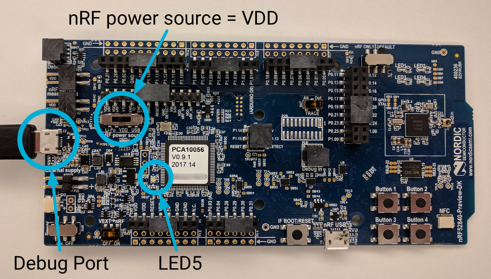
將 USB 傳輸線插入 nRF52840 主機板外部電源接腳旁的 Micro-USB 偵錯連接埠,再將 USB 傳輸線插入 Linux 電腦。設定正確無誤,且 LED5 已開啟。
和先前一樣,記下 nRF52840 主機板的序號:
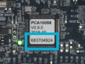
前往 nRFx 指令列工具的位置,使用主機板序號將 OpenThread CLI FTD 十六進位檔案刷新到 nRF52840 主機板上:
$ cd ~/nrfjprog
$ ./nrfjprog -f nrf52 -s 683704924 --verify --chiperase --program \
       ~/openthread/output/nrf52840/bin/ot-cli-ftd.hex --reset
閃爍時,LED 燈會短暫關閉。成功時,會產生以下輸出內容:
Parsing hex file.
Erasing user available code and UICR flash areas.
Applying system reset.
Checking that the area to write is not protected.
Programing device.
Applying system reset.
Run.
重複這部「刷新主機」原本只提供兩個面板每個 Jamboard 都必須以相同方式連線至 Linux 電腦,且閃爍的指令會相同,但主機板序號除外。務必使用每個主板專屬的序號
nrfjprog 刷新指令。
如果成功,LED 燈、LED 2 或 LED 3。你甚至可能會在刷新 (裝置角色變更功能) 後,立即看到 LED 燈的指示燈從 3 切換成 2 (或 2 到 1)。
12. 應用程式功能
這三個 nRF52840 主機板現在應該都已通電,並開始執行我們的 OpenThread 應用程式。如先前所述,這個應用程式有兩個主要功能。
裝置角色指標
每個電路板的 LED 燈反映了 Thread 節點目前的角色:
- LED1 = 領導者
- LED2 = 路由器
- LED 3 = 終端裝置
隨著角色改變,LED 燈也會亮起。每部裝置開機後 20 秒內,應該就會在遊戲板上看到這些變更。
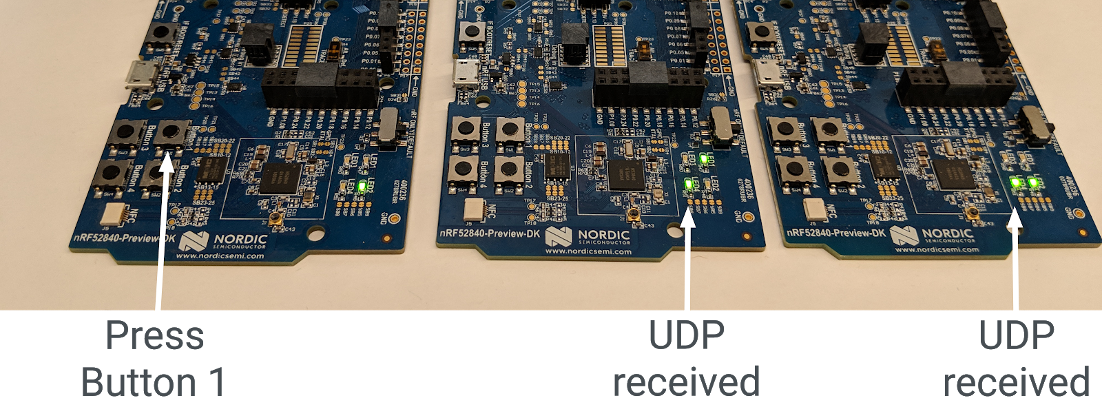
UDP 多點傳播
在白板上按下 Button1 時,系統會將 UDP 訊息傳送至網狀本機多點傳送位址,其中包含 Thread 網路中的所有其他節點。為了收到這則訊息,所有其他 Jamboard 上的 LED4 會切換為開啟或關閉。各電路板的 LED 燈會保持開啟或關閉,直到收到其他 UDP 訊息為止。
13. 示範:觀察裝置角色變更
你刷新的裝置是某種完整 Thread 裝置 (FTD),稱為路由器符合資格的終端裝置 (REED)。也就是說,這類裝置可以做為路由器或終端裝置使用,也可將自身從終端裝置升級為路由器。
Thread 最多可支援 32 個路由器,但會試著將路由器數量保持在 16 和 23 之間。如果 REED 以終端裝置所連接,且路由器數量低於 16,則會自動升級為路由器。此變更應在您在應用程式中設定 otThreadSetRouterSelectionJitter 值 (20 秒) 的秒數內隨機發生,
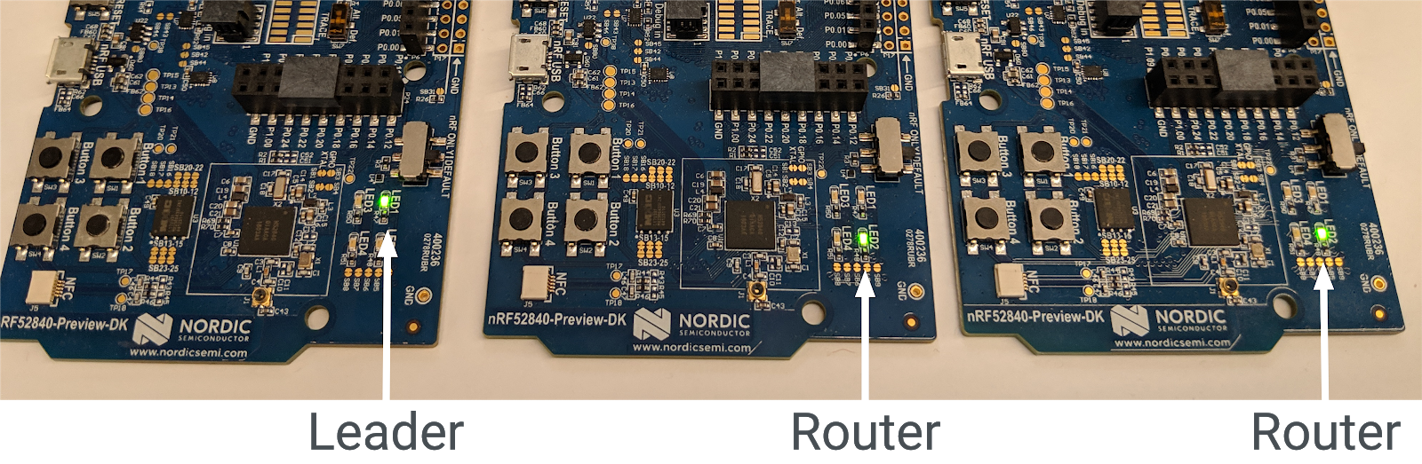
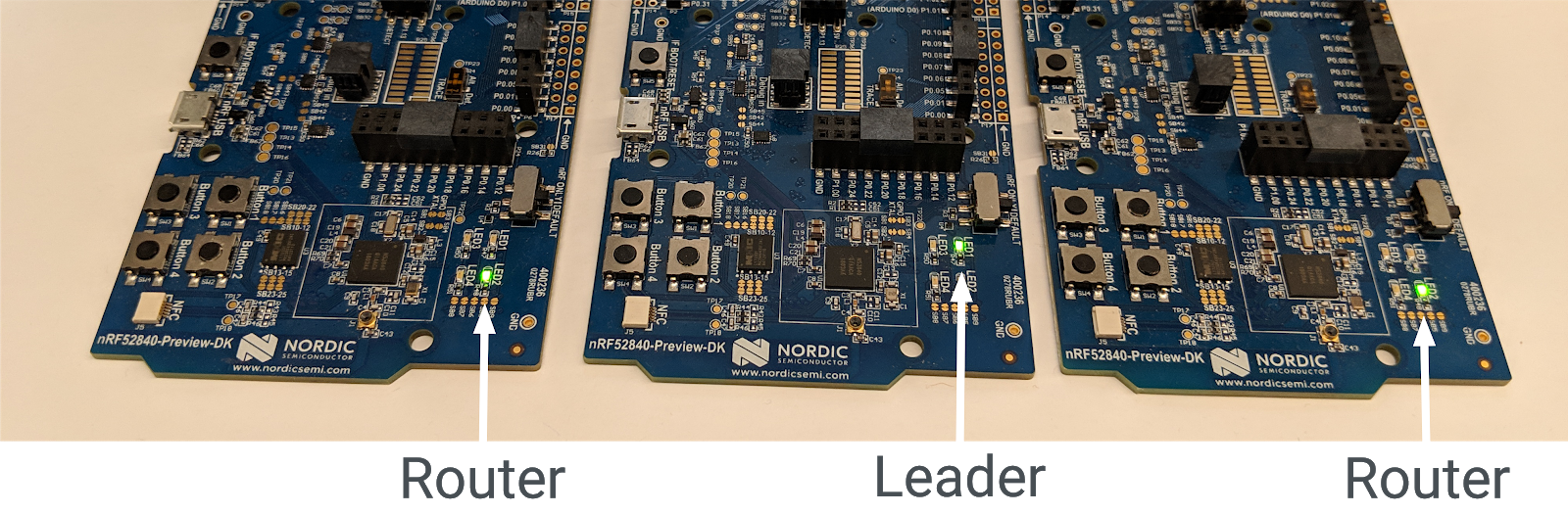
每個 Thread 網路也都有一個主要網路,後者負責管理 Thread 網路中的路由器組合。所有裝置都開啟後,在 20 秒後,其中一部裝置應為領導者 (開啟 LED1),另外兩個裝置應為路由器 (LED 燈已開啟)。
移除主管
如果 Thread 網路中的領導者遭到移除,其他路由器會將自己升級為領導者,藉此確保網路仍具有領導者。
使用電源開關關閉領導板 (顯示 LED1 燈的燈)。等待約 20 秒。在剩下的兩個電路板中,LED 燈 (Router) 會關閉,LED LED 燈 (Leader) 也會開啟。這部裝置目前是 Thread 網路的領導者。
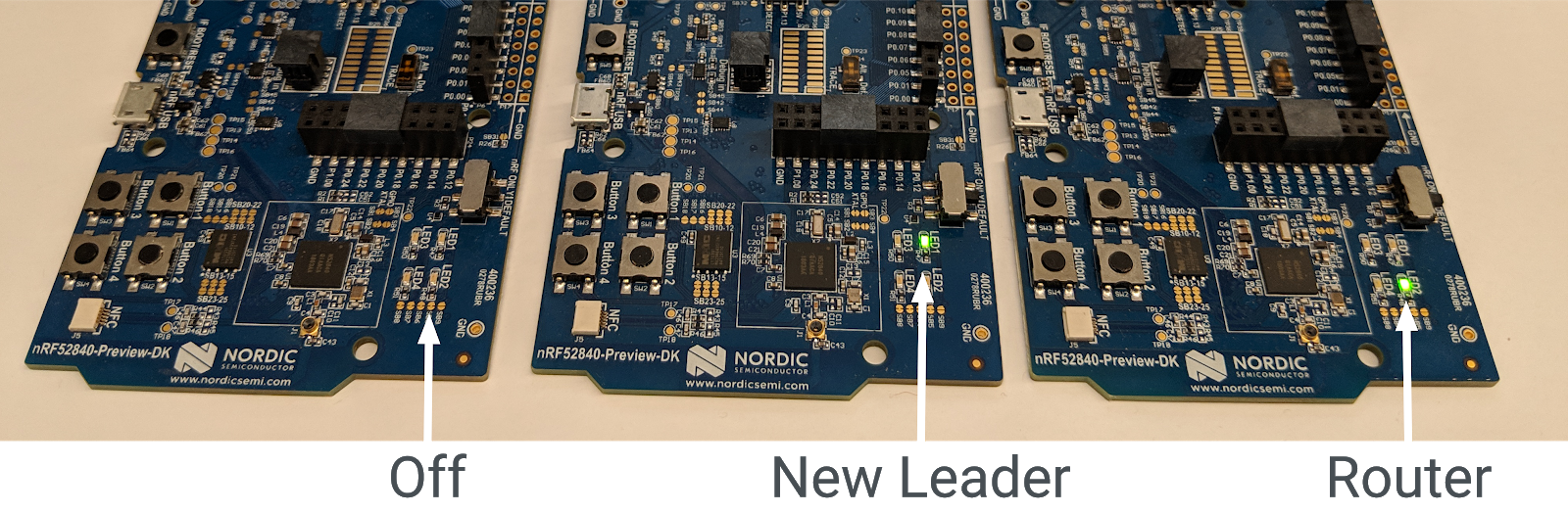
重新開啟原先的領導者看板。Thread 網路應該會自動重新連接 Thread 網路,做為結束裝置 (LED 燈亮起)。系統會在 20 秒內 (「路由器選擇吉特」) 將自身升級為路由器 (LED 燈亮起)。
重設主面板
請關閉所有三個電路板,然後再次開啟,並觀察 LED 燈。第一個搭載電源的電路板應以領導人角色 (LED1 燈亮起) 為主,Thread 網路中的第一個路由器會自動成為領導者。
另外兩個主機板,在 LED 燈 (亮燈) 時連線至網路,但應在 20 秒內將自身升級為路由器 (LED 燈亮起)。
網路分區
如果 Jamboard 電力不足,或是 Thread 網路之間的無線電連線訊號微弱,Thread 網路可能會分割成多個分區,並可能將多部裝置顯示為領導者。
由於 Thread 可自行修復,因此分區最終應合併為單一分區,並呈現一位領導人。
14. 示範:傳送 UDP 多點傳送
如果繼續之前的運動,則 LED 4 不應在任何裝置上亮起。
選擇遊戲板,然後按下 Button1。凡是執行應用程式的 Thread 網路中其他 Jamboard 上的 LED 燈,應該都會切換狀態。如果繼續進行之前的練習,現在應會處於開啟狀態。
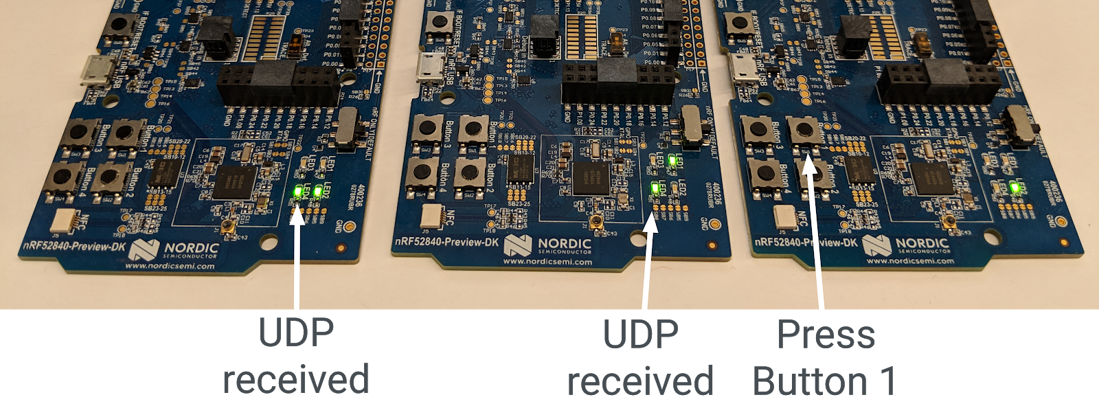
再次按下同一個遊戲板的 按鈕 1。所有其他 Jamboard 的 LED 燈應會再次切換。
按下其他主機板上的 Button1,觀察其他主機板上的 LED 燈切換鈕。在其中一個 LED4 目前所在的主機板上,按下 Button1。該 Jamboard 的 LED 燈會保持開啟,但在其他平台上有開關。
網路分區
如果董事會經過分區,且其中有多個領先者,各板的多點傳播訊息結果就會有所不同。如果您在已分區 Thread 網路的主面板上按下 Button1,其他主機板上的 LED 指示燈將不會亮起。如果發生這種情況,請重設 Jamboard,理想情況下,主機板應重新組成一個 Thread 網路,且 UDP 訊息應可正常運作。
15. 恭喜!
您已成功建立使用 OpenThread API 的應用程式!
您已經知道:
- 如何在 Nordic nRF52840 開發板上設計按鈕和 LED 燈
- 如何使用常見的 OpenThread API 和
otInstance類別 - 如何監控及回應 OpenThread 狀態變更
- 如何將 UDP 訊息傳送至 Thread 網路中的所有裝置
- 如何修改 Makefiles
後續步驟
以本程式碼研究室為基礎,嘗試下列練習:
- 修改 GPIO 模組,使用 GPIO 接腳 (而非內建的 LED),並連接可根據路由器角色改變顏色的外部 RGB LED
- 為其他範例平台新增 GPIO 支援
- 使用 Router/Leader API 搜尋個別裝置並連線偵測 (ping),而不要透過按下多點按鈕對所有裝置進行連線偵測 (ping)
- 使用 OpenThread 邊界路由器將網狀網路連至網際網路,並從 Thread 網路外的多點傳送器對 LED 發光
延伸閱讀
歡迎前往 openthread.io 和 GitHub 查看各種 OpenThread 資源,包括:
- 支援平台 - 找出所有支援 OpenThread 的平台
- 建構 OpenThread - 進一步瞭解建構及設定 OpenThread
- Thread Primer - 關於 Thread 概念的絕佳參考資料
參考資料: