
1. Introduction

Google's OpenThread (OT) is an open-source implementation of Thread. Google has released OpenThread to make the networking technology used in Google Nest products broadly available to developers, accelerating development of products for the connected home and commercial building applications. With a narrow platform abstraction layer and a small memory footprint, OpenThread is highly portable. It supports both system-on-chip (SoC) and network co-processor (NCP) designs.
The Thread Specification defines an IPv6-based reliable, secure, and low-power wireless device-to-device communication protocol for home and commercial building applications.
Texas Instruments has implemented OpenThread for the SimpleLink™ CC27xx device family. The ot-ti repository on GitHub contains the platform drivers and example applications needed to run OpenThread on Texas Instruments SimpleLink Connected MCUs. The CC2745R10-Q1 is an automotive-grade (AEC-Q100 qualified), Thread-certified IEEE 802.15.4 wireless MCU from TI's SimpleLink CC27xx family.
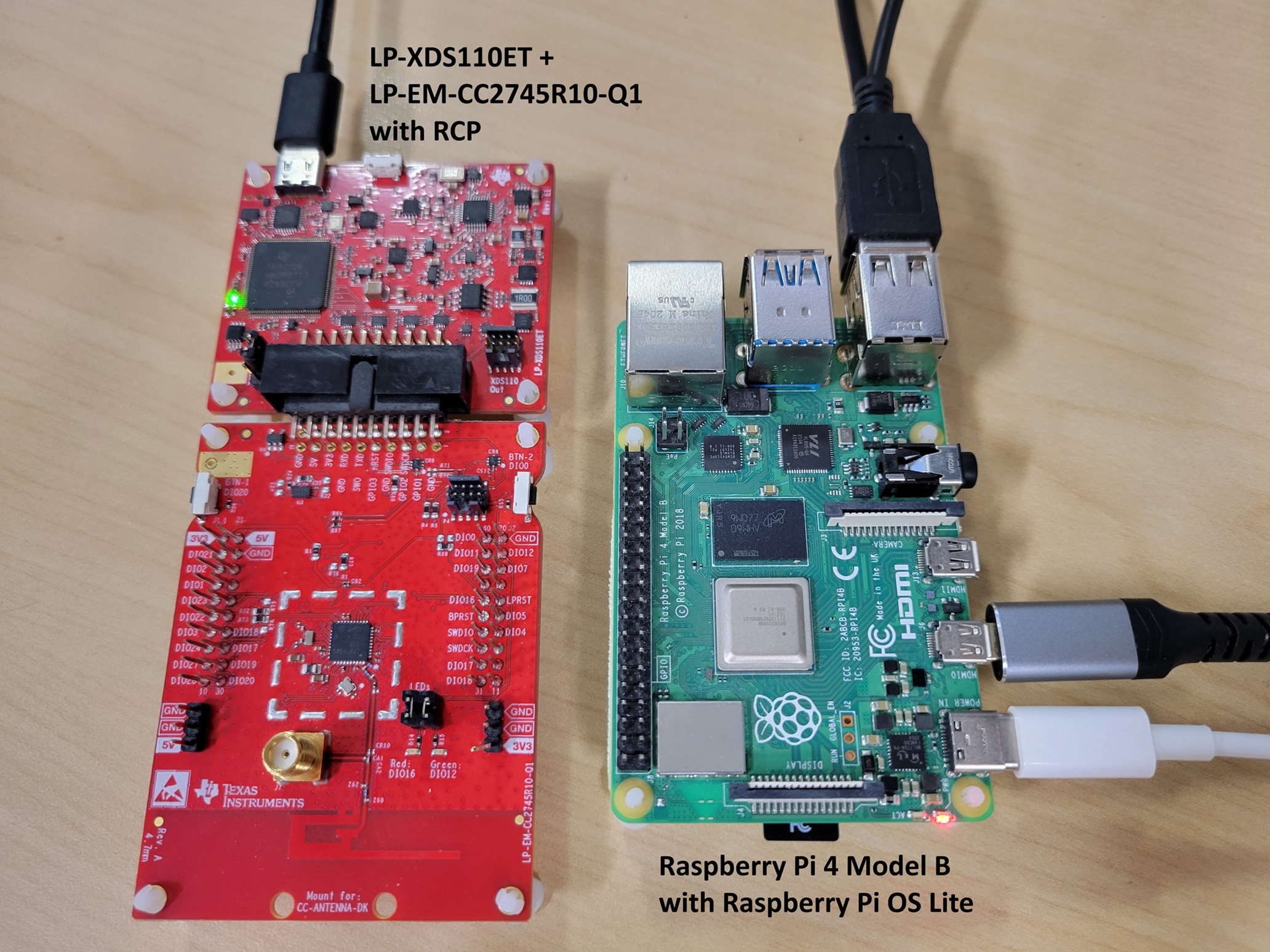
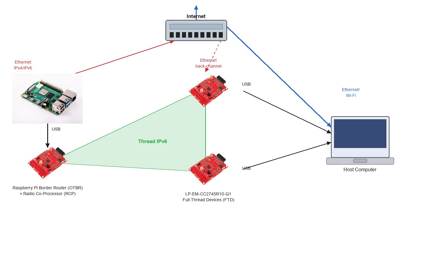
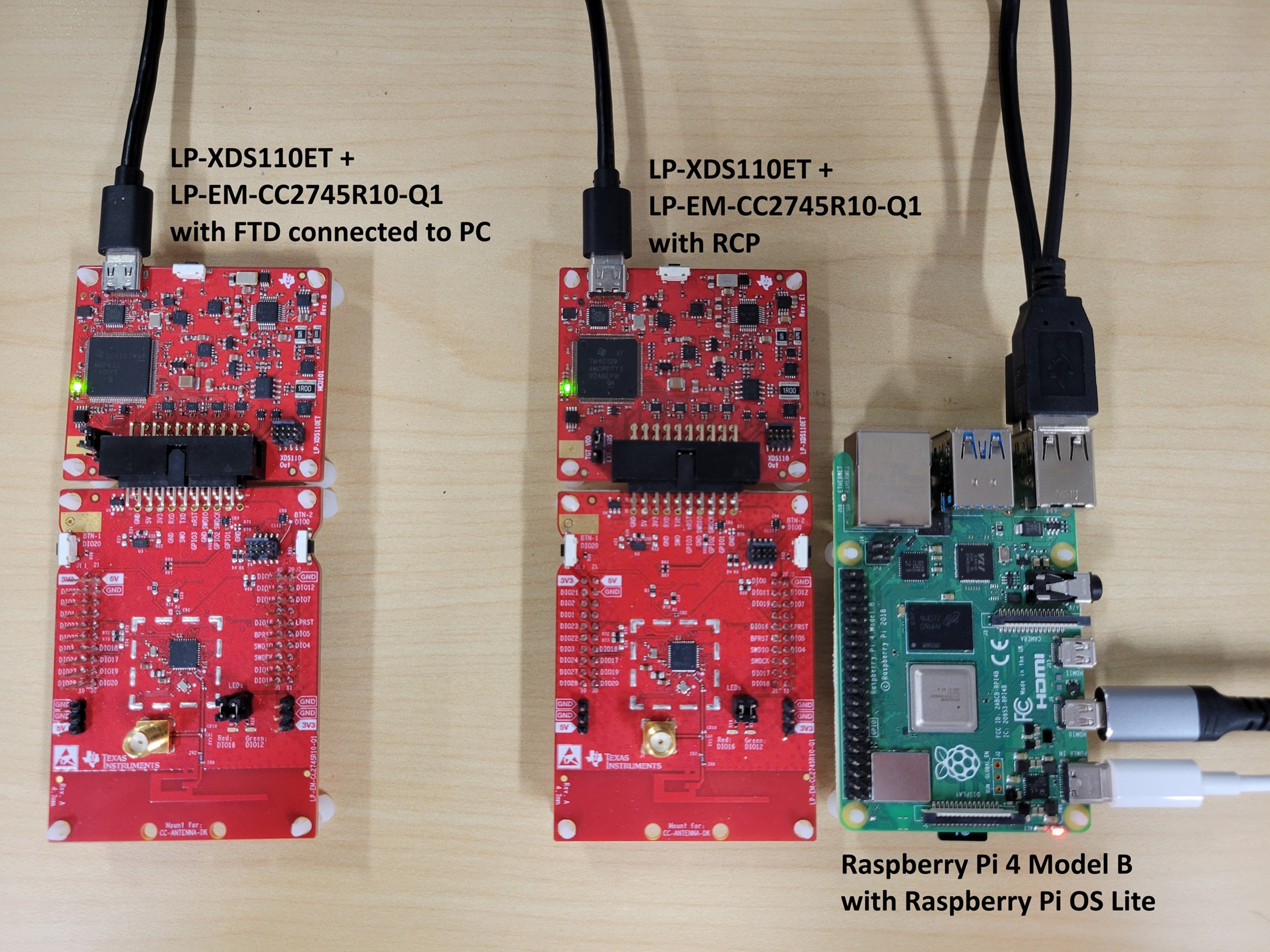
This codelab describes how to get started developing OpenThread applications with the LP-EM-CC2745R10-Q1 LaunchPad evaluation board and the ot-ti repository. The image below shows the hardware setup used in this codelab, with an OT Border Router (OTBR) and two Thread Full Thread Devices (FTDs).
What you'll learn
- How to set up the Texas Instruments ot-ti build environment.
- How to build and flash OpenThread CLI binaries to LP-EM-CC2745R10-Q1 boards.
- How to set up a Raspberry Pi as an OpenThread Border Router (OTBR) using ot-br-posix.
- How to create a Thread network on the OTBR.
- Out-of-band commissioning of devices onto a Thread network.
- How to verify Thread communication between nodes using the ping command.
2. Prerequisites
Hardware
- 3 LP-EM-CC2745R10-Q1 LaunchPad boards: one configured as an RCP connected to the Border Router, and two configured as Full Thread Devices (FTD).
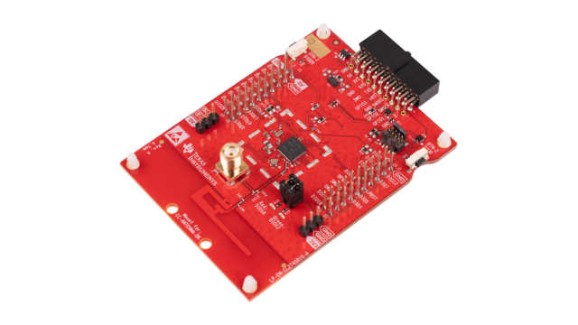 The CC2745R10-Q1 is an automotive-grade (AEC-Q100 qualified) Thread-certified IEEE 802.15.4 wireless MCU in TI's SimpleLink CC27xx family. The LP-EM-CC2745R10-Q1 is the corresponding LaunchPad Evaluation Module and supports RCP, FTD, MTD, and NCP Thread roles. The CC2340R5 with the LP-EM-CC2340R5 LaunchPad is a lower memory option that can serve as the RCP only. It does not support FTD, MTD, or NCP roles. If you substitute an LP-EM-CC2340R5 for Board 1 (RCP), the two FTD boards must still be LP-EM-CC2745R10-Q1.
 - 3 LP-XDS110ET debug probes: one per LaunchPad board, used for programming and debug over USB.
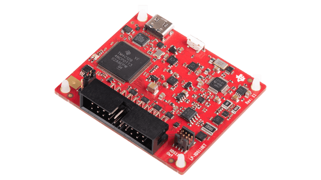 The LP-XDS110ET is a separate USB debug probe required for LaunchPads in the LP-EM form factor. It includes EnergyTrace support for power profiling. The LP-XDS110 is a lower-cost alternative that provides the same programming and debug capability but does not include EnergyTrace. As a further alternative, a LaunchPad with an on-board XDS110 debug probe (such as the LAUNCHXL-CC26X2R1) can be used in place of the LP-EM board and a separate debug probe entirely. See the LaunchPad debug connectivity guide for details.
 - 3 micro-USB cables to connect and power the LaunchPad boards and debug probes.
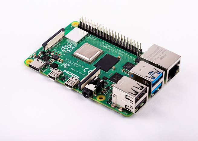
- A Raspberry Pi 4B or greater with Raspberry Pi OS connected to the internet over Ethernet. This will be configured as the OT Border Router host.
- A Linux or macOS host system with at least 2 USB ports and internet access. The build environment requires a Bash-compatible shell. Windows users should use WSL2 (Windows Subsystem for Linux 2) with Ubuntu.
- At least one Ethernet cable for connecting the Raspberry Pi to the internet. Alternatively, you can connect the Raspberry Pi to Wi-Fi and use
wlan0as the infrastructure interface — see the OTBR setup step for details.
Software
- TI ot-ti repository: https://github.com/TexasInstruments/ot-ti
- GNU ARM Embedded Toolchain 12.2 (installed automatically by the bootstrap script)
- SysConfig 1.27.0 (installed automatically by the bootstrap script)
- TI UniFlash: for flashing firmware to the LaunchPad boards
- ot-br-posix: https://github.com/openthread/ot-br-posix
- A serial terminal such as PuTTY (Windows), minicom (Linux), or screen (macOS/Linux)
3. Hardware Setup
This codelab uses three LP-EM-CC2745R10-Q1 boards:
- Board 1 (RCP): Runs
ot-rcpfirmware. Connected to the Raspberry Pi via USB as the radio co-processor for the Border Router. - Board 2 (FTD 1): Runs
ot-cli-ftdfirmware as a Full Thread Device. - Board 3 (FTD 2): Runs
ot-cli-ftdfirmware as a Full Thread Device.
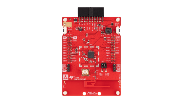
Connect each LaunchPad to your host computer via micro-USB. The USB connection provides both power and debug/programming capability through the onboard XDS110 debug probe.
Each LP-EM-CC2745R10-Q1 appears as two virtual serial ports when connected via USB: one for the XDS110 debug interface and one for the application UART. When opening a serial console, connect to the Application/User UART port, not the Auxiliary Data port.
4. Repository Setup and Build
The ot-ti build system uses CMake and requires a Bash shell. All commands in this section are run on the Linux or macOS host (or WSL2 on Windows).
1. Clone the repository
$ git clone https://github.com/TexasInstruments/ot-ti.git
$ cd ot-ti
$ git submodule update --init
2. Run the bootstrap script
The bootstrap script installs required dependencies including the GNU ARM toolchain and SysConfig:
$ ./script/bootstrap
The bootstrap script requires cmake, git, wget, and standard build tools. On Ubuntu/Debian, install prerequisites with: sudo apt-get install -y cmake git make wget tar ninja-build
3. Build firmware for LP_EM_CC2745R10_Q1
Build all firmware images for the LP-EM-CC2745R10-Q1 board:
$ ./script/build LP_EM_CC2745R10_Q1
The LP_EM_CC2745R10_Q1 build target corresponds to the CC2745R10-Q1 device in the CC27xx SimpleLink family (Arm Cortex-M33F core). To see all supported boards, run ./script/build without arguments.
After a successful build, ELF binaries are in build/bin/:
$ ls build/bin/
ot-cli-ftd.out  ot-cli-mtd.out  ot-ncp-ftd.out  ot-rcp.out
The two images used in this codelab are:
ot-rcp.out: Radio Co-Processor firmware for the Border Router board.ot-cli-ftd.out: Full Thread Device CLI firmware for the two FTD boards.
Optional Minimal Thread Device: If you want to explore a sleepy end device instead of a Full Thread Device, you can flash ot-cli-mtd.out in place of ot-cli-ftd.out on Boards 2 and 3. An MTD does not route Thread traffic and can enter low-power sleep states, making it well suited for battery-powered applications. The Thread network formation steps in this codelab are the same for both device types.
Optional Network Co-Processor (NCP): The ot-ncp-ftd.out binary implements the NCP architecture, where the OpenThread stack runs on the device and a host processor drives it via the Spinel protocol. NCP usage is outside the scope of this codelab, refer to the NCP README for details.
5. Flash Firmware
Use TI UniFlash to flash the ELF images to the LaunchPad boards.
Flash using UniFlash
- Open UniFlash. Connected LaunchPad boards are displayed under Detected Devices due to the automatic device detection feature.If your board is not detected automatically, click New Configuration, select the
LP-EM-CC2745R10-Q1target, and choose the XDS110 USB debug probe.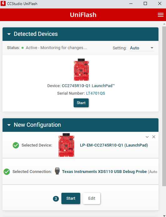
- Select Board 1 (to be flashed with
ot-rcp.out) and click Start. - Click the Browse button and navigate to
ot-ti/build/bin/ot-rcp.out.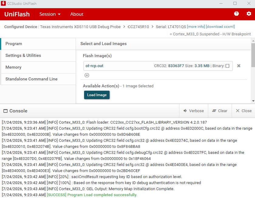
- Click Load Image to flash the firmware. The log area shows progress and confirms completion.
- Repeat steps 2–4 for Board 2 and Board 3, selecting
ot-ti/build/bin/ot-cli-ftd.outfor each.
Alternative: Flash using Code Composer Studio (CCS)
Code Composer Studio can be used as an alternative to UniFlash, and additionally provides a full debug environment:
- Download and install Code Composer Studio.
- Create a target connection (CCXML) for the LP-EM-CC2745R10-Q1 with the XDS110 debugger. Refer to the CCS User's Guide: Manual Method.
- Start a project-less debug session as described in CCS User's Guide: Manual Launch.
- Connect to the Arm Cortex-M33 core and click Load to load the ELF image.
The default CCXML configuration uses 2-wire cJTAG to match the default LP-EM-CC2745R10-Q1 jumper configuration. After programming via JTAG, power-cycle the board to clear the halt-in-boot flag.
6. Program the HSM
The CC2745R10-Q1 contains a Hardware Security Module (HSM) that must be provisioned before running Thread or other secure application firmware. If your LP-EM-CC2745R10-Q1 board has not yet had its HSM programmed, complete this step now.
To program the HSM using UniFlash:
- Open UniFlash and select your LP-EM-CC2745R10-Q1 board from Detected Devices.
- Navigate to the HSM programming panel and load the HSM firmware image as shown below.
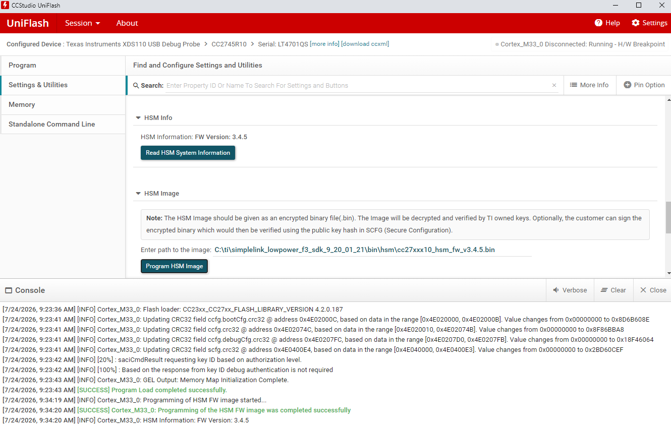
- Follow the on-screen prompts to complete HSM provisioning. The operation is logged in the UniFlash output console.
Refer to the CC2745R10-Q1 Quick Start Guide in TI Resource Explorer for the complete HSM programming procedure, including the required firmware image path within the SimpleLink Low Power F3 SDK.
7. Firmware Summary
At this point, all three boards should be flashed:
- Board 1:
ot-rcp.out: Disconnect from the host computer and connect to the Raspberry Pi via USB. - Board 2:
ot-cli-ftd.out: Keep connected to the host computer. - Board 3:
ot-cli-ftd.out: Keep connected to the host computer.
Your hardware setup will look like the diagram below. Board 1 connects to the Raspberry Pi as the radio co-processor for the OTBR, while Boards 2 and 3 remain connected to the host computer for serial console access.
8. Set Up Serial Console for ot-cli-ftd Devices
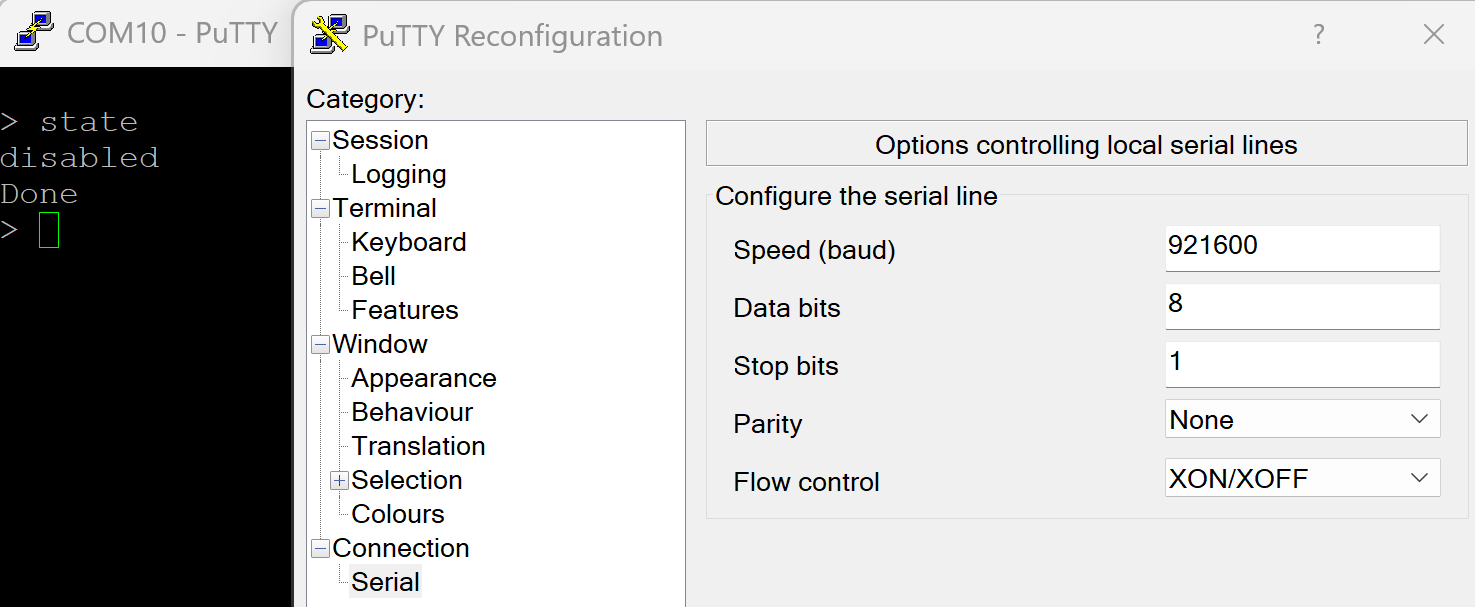
The LP-EM-CC2745R10-Q1 exposes the application UART via USB at 921600 baud.
Open a serial terminal to the Application UART COM port (Windows) or /dev/ttyACM* device (Linux/macOS) for each FTD board using these settings:
Parameter | Value |
Speed (baud) |
|
Data bits |
|
Stop bits |
|
Parity |
|
Flow control |
|
Tip (Linux/macOS): Identify the correct device node by running ls /dev/ttyACM* before and after plugging in a board and noting which entry appears. Each LP-EM-CC2745R10-Q1 creates two entries: the lower-numbered port is the XDS110 debug UART and the higher-numbered port is the Application UART. For example, if the board creates /dev/ttyACM0 and /dev/ttyACM1, use /dev/ttyACM1.
Tip (Windows): Open Device Manager and look under Ports (COM & LPT) for two new COM ports when a board is plugged in. The XDS110 debug data port typically appears first, use the second (higher-numbered) COM port for the application console.
Press Enter in the terminal to get an OpenThread CLI prompt (>). For a full list of available commands, see the OpenThread CLI Reference. Verify the FTD is operational:
> state
disabled
Done
You will not yet set up a serial console for the RCP board. The OTBR on the Raspberry Pi communicates with the RCP directly. In the next step, you will configure the Raspberry Pi as the OpenThread Border Router.
9. Set Up the Raspberry Pi as a Border Router
The OTBR is built from ot-br-posix, the open-source OpenThread Border Router project. The Border Router runs on the Raspberry Pi and uses Board 1 (RCP) as its 802.15.4 radio via USB.
Raspberry Pi Setup
- Flash Raspberry Pi OS (64-bit Lite or Desktop) to your SD card using Raspberry Pi Imager.
- Boot the Raspberry Pi and open a terminal (via SSH or directly).
- Update the package manager and upgrade installed packages:
$ sudo apt-get update
$ sudo apt-get upgrade -y
Reboot the Raspberry Pi after updates before proceeding: sudo reboot
Connect Board 1 (RCP) to the Raspberry Pi
Connect Board 1 (flashed with ot-rcp) to the Raspberry Pi via micro-USB. After connection, verify the device node appears:
$ ls /dev/ttyACM*
/dev/ttyACM0
/dev/ttyACM1
The Application UART of the RCP board is typically /dev/ttyACM1 (the XDS110 debug UART is /dev/ttyACM0). Verify which port is the application UART by checking that it responds when the OTBR agent is started in a later step. If other USB serial devices are connected, the device node number may differ. Adjust the path in the OTBR configuration accordingly.
Build and Install ot-br-posix
On the Raspberry Pi, clone and build ot-br-posix:
$ git clone https://github.com/openthread/ot-br-posix.git
$ cd ot-br-posix
$ ./script/bootstrap
Run the setup script, specifying your Ethernet interface as the backbone (infrastructure) interface:
$ INFRA_IF_NAME=eth0 ./script/setup
eth0 is the typical name for the wired Ethernet interface. If you are connecting the Raspberry Pi via Wi-Fi instead of Ethernet, replace eth0 with wlan0 (and ensure the Pi is already connected to your Wi-Fi network). Verify the active interface name with ip link show.
The setup script builds ot-br-posix from source, installs the otbr-agent and otbr-web system services, and configures the networking stack. This process typically takes 10–20 minutes on a Raspberry Pi 4B.
Configure the OTBR Agent
Edit the OTBR agent configuration file to specify the RCP device path and baud rate:
$ sudo nano /etc/default/otbr-agent
Locate the OTBR_AGENT_OPTS line and update it to reference the RCP Application UART:
OTBR_AGENT_OPTS="-I wpan0 -B eth0 spinel+hdlc+uart:///dev/ttyACM1?uart-baudrate=921600"
Replace eth0 with wlan0 if your Raspberry Pi is connected via Wi-Fi.
OTBR_AGENT_OPTS="-I wpan0 -B wlan0 spinel+hdlc+uart:///dev/ttyACM1?uart-baudrate=921600"
The LP-EM-CC2745R10-Q1 RCP Application UART operates at 921600 baud. Verify the device path (/dev/ttyACM1 in this example) matches the Application UART of your RCP board.
Restart the OTBR agent to apply the configuration:
$ sudo systemctl restart otbr-agent
$ sudo systemctl enable otbr-agent
Verify the agent is running:
$ sudo systemctl status otbr-agent
Interact with the RCP Node
Communicate with the RCP node using the ot-ctl tool:
$ sudo ot-ctl state
disabled
Done
You can monitor the OTBR agent log for connection and status messages:
$ sudo journalctl -u otbr-agent -f
Optionally, the OTBR web interface is available at http:// and provides a graphical view of the Thread network.
To stop or restart the OTBR agent:
$ sudo systemctl stop otbr-agent
$ sudo systemctl start otbr-agent
At this point you should have three active consoles:
- Serial terminal for Board 2 (
ot-cli-ftd 1) on the host computer. - Serial terminal for Board 3 (
ot-cli-ftd 2) on the host computer. - SSH or terminal session on the Raspberry Pi for
ot-ctl(OTBR/RCP).
You are now ready to form a Thread network.
10. Create a Thread Network
Set Up RCP (OTBR)
Create a new Thread network from the ot-ctl shell on the Raspberry Pi. Enter the following commands in order:
Index | Command | Description | Expected Response | ||
1 |
| Create a new network configuration. | Done | ||
2 |
| Commit new dataset to the Active Operational Dataset. | Done | ||
3 |
| Enable Thread interface. | Done | ||
4 |
| Enable and attach Thread protocol operation. | Done | ||
Wait 10 seconds for the Thread interface to come up. | |||||
5 |
| Check the device state. It should be leader. Other possible states: offline, disabled, detached, child, router, or leader. | leader | ||
6 |
| View the network configuration. Your values will differ. Note the channel, network key, network name, and PAN ID — these are needed to join FTDs to the network. | Active Timestamp: 1 | ||
Add FTDs to the Thread Network (Out-of-Band Method)
Using the out-of-band commissioning method, you provide the network credentials directly. In the serial terminal for each FTD board, enter the following commands using the channel and network key from the OTBR dataset output above:
Index | Command | Description | Expected Response | ||
1 |
| Set the channel to match the OTBR. Replace | Done | ||
2 |
| Set the network key. Replace with your OTBR's network key. Only this key is required to attach. | Done | ||
3 |
| Commit new dataset to the Active Operational Dataset. | Done | ||
4 |
| Enable Thread interface. | Done | ||
5 |
| Enable and attach Thread protocol operation. | Done | ||
Wait 20 seconds while the device joins and configures itself. | |||||
6 |
| Check device state. | child | ||
Because of the self-configuring nature of Thread networks and these being Full Thread Devices, either or both FTDs may eventually become routers. You can verify the current role at any time with the state command.
Communication Between Thread Devices
Use the ping command to verify that devices can communicate. Get the IPv6 addresses of each device with ipaddr:
> ipaddr
fd5c:c6b:3a17:40b9:0:ff:fe00:fc00		# Leader Anycast Locator (ALOC)
fd5c:c6b:3a17:40b9:0:ff:fe00:1800		# Routing Locator (RLOC)
fd5c:c6b:3a17:40b9:84e2:bae8:bd5b:fa03		# Mesh-Local EID (ML-EID)
fe80:0:0:0:c449:ca4a:101f:5d16			# Link-Local Address (LLA)
Done
From both FTDs, ping the OTBR using its RLOC address:
> ping fd5c:c6b:3a17:40b9:0:ff:fe00:1800
Done
>
> 16 bytes from fd5c:c6b:3a17:40b9:0:ff:fe00:1800: icmp_seq=3 hlim=64 time=30ms
16 bytes from fd5c:c6b:3a17:40b9:0:ff:fe00:1800: icmp_seq=3 hlim=64 time=52ms
A successful response confirms the Thread network is operating and devices can communicate. Repeat the process to ping each FTD from the OTBR (sudo ot-ctl ping ).
11. Congratulations
You've created a Thread network with TI CC2745R10-Q1 boards!
You now know:
- How to set up the Texas Instruments ot-ti build environment.
- How to build and flash OpenThread CLI binaries to the LP-EM-CC2745R10-Q1 LaunchPad.
- How to set up a Raspberry Pi as an OpenThread Border Router (OTBR) using ot-br-posix.
- How to create a Thread network on the OTBR.
- Out-of-band commissioning of devices onto a Thread network.
- How to verify Thread communication between nodes using the ping command.
Further Reading
Check out openthread.io and GitHub for a variety of OpenThread resources, including:
- Supported Platforms — discover all the platforms that support OpenThread
- Build OpenThread — further details on building and configuring OpenThread
- Thread Primer — covers all the Thread concepts featured in this codelab
- TI ot-ti Repository — TI's OpenThread implementation for SimpleLink devices, with build instructions and release notes
- CC2745R10-Q1 Product Page — device datasheet, reference designs, and other documentation
- LP-EM-CC2745R10-Q1 LaunchPad — evaluation board user guide and hardware files
- OpenThread CLI Reference — overview of the OpenThread CLI and its usage
- OpenThread CLI Commands — complete reference for all OpenThread CLI commands
- TI E2E Community — Thread & Zigbee — technical support community for Texas Instruments wireless connectivity products