
1. 简介

由 Nest 发布的 OpenThread 是 Thread® 网络协议的开源实现。Nest 发布了 OpenThread,以便开发者广泛使用 Nest 产品中使用的技术,从而加快智能互联家居产品的开发。
Thread 规范定义了一种基于 IPv6 的可靠、安全且低功耗的无线设备到设备通信协议,适用于家庭应用。OpenThread 实现所有 Thread 网络层,包括 IPv6、6LoWPAN、具有 MAC 安全性的 IEEE 802.15.4、网状链路建立和网状路由。
在此 Codelab 中,您将使用 OpenThread API 来启动 Thread 网络、监控设备角色变化并做出相应反应、发送 UDP 消息,以及将这些操作与实际硬件上的按钮和 LED 相关联。
学习内容
- 如何对 Nordic nRF52840 开发板上的按钮和 LED 进行编程
- 如何使用常见的 OpenThread API 和
otInstance类 - 如何监控和响应 OpenThread 状态变化
- 如何向 Thread 网络中的所有设备发送 UDP 消息
- 如何修改 Makefile
所需条件
硬件:
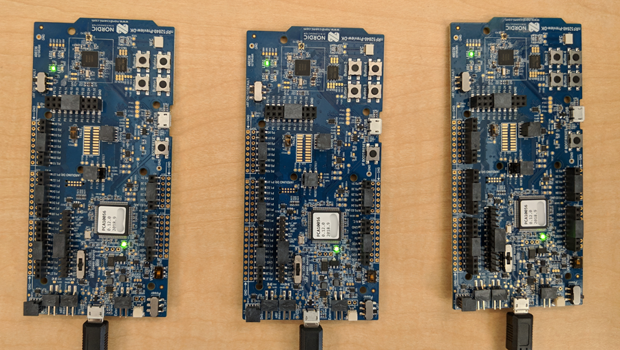
- 3 个 Nordic Semiconductor nRF52840 开发板
- 3 根 USB 转 Micro-USB 线缆,用于连接板
- 一台具有至少 3 个 USB 端口的 Linux 机器
软件:
- GNU 工具链
- Nordic nRF5x 命令行工具
- Segger J-Link 软件
- OpenThread
- Git
除非另有说明,否则本 Codelab 的内容已根据知识共享署名 3.0 许可获得了许可,并且代码示例已根据 Apache 2.0 许可获得了许可。
2. 使用入门
完成硬件 Codelab
在开始此 Codelab 之前,您应先完成 使用 nRF52840 板和 OpenThread 构建 Thread 网络 Codelab,该 Codelab:
- 详细说明了构建和刷写所需的全部软件
- 教您如何构建 OpenThread 并将其刷写到 Nordic nRF52840 板上
- 演示 Thread 网络的基础知识
本 Codelab 中未详细介绍构建 OpenThread 和刷写开发板所需的任何环境设置,仅提供了刷写开发板的基本说明。假设您已完成“构建 Thread 网络”Codelab。
Linux 机器
此 Codelab 旨在通过基于 i386 或 x86 的 Linux 机器刷写所有 Thread 开发板。所有步骤已在 Ubuntu 14.04.5 LTS (Trusty Tahr) 上进行了测试。
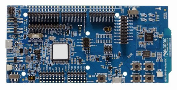
Nordic Semiconductor nRF52840 板
此 Codelab 使用三个 nRF52840 PDK 板。
安装软件
如需构建和刷写 OpenThread,您需要安装 SEGGER J-Link、nRF5x 命令行工具、ARM GNU 工具链和各种 Linux 软件包。如果您已按要求完成“构建 Thread 网络”Codelab,则已安装所需的一切。如果没有,请先完成该 Codelab,然后再继续,以确保您可以构建 OpenThread 并将其刷写到 nRF52840 开发板。
3. 克隆代码库
OpenThread 随附了示例应用代码,您可以将其用作此 Codelab 的起点。
克隆 OpenThread Nordic nRF528xx 示例代码库并构建 OpenThread:
$ git clone --recursive https://github.com/openthread/ot-nrf528xx
$ cd ot-nrf528xx
$ ./script/bootstrap
4. OpenThread API 基础知识
OpenThread 的公共 API 位于 OpenThread 代码库中的 ./openthread/include/openthread。这些 API 可在 Thread 级和平台级提供对各种 OpenThread 特性和功能的访问权限,以便在您的应用中使用:
- OpenThread 实例信息和控制
- 应用服务,例如 IPv6、UDP 和 CoAP
- 网络凭据管理,以及 Commissioner 和 Joiner 角色
- 边界路由器管理
- 增强功能,例如儿童监督和干扰检测
您可以在 openthread.io/reference 上找到所有 OpenThread API 的参考信息。
使用 API
如需使用某个 API,请在您的某个应用文件中添加其头文件。然后调用所需函数。
例如,OpenThread 随附的 CLI 示例应用使用以下 API 标头:
./openthread/examples/apps/cli/main.c
#include <openthread/config.h>
#include <openthread/cli.h>
#include <openthread/diag.h>
#include <openthread/tasklet.h>
#include <openthread/platform/logging.h>
OpenThread 实例
在处理 OpenThread API 时,您会经常使用 otInstance 结构。初始化后,此结构表示 OpenThread 库的静态实例,并允许用户进行 OpenThread API 调用。
例如,OpenThread 实例在 CLI 示例应用的 main() 函数中初始化:
./openthread/examples/apps/cli/main.c
int main(int argc, char *argv[])
{
    otInstance *instance

...

#if OPENTHREAD_ENABLE_MULTIPLE_INSTANCES
    // Call to query the buffer size
    (void)otInstanceInit(NULL, &otInstanceBufferLength);

    // Call to allocate the buffer
    otInstanceBuffer = (uint8_t *)malloc(otInstanceBufferLength);
    assert(otInstanceBuffer);

    // Initialize OpenThread with the buffer
    instance = otInstanceInit(otInstanceBuffer, &otInstanceBufferLength);
#else
    instance = otInstanceInitSingle();
#endif

...

    return 0;
}
特定于平台的函数
如果您想向 OpenThread 随附的某个示例应用添加特定于平台的功能,请先在 ./openthread/examples/platforms/openthread-system.h 标头中声明这些功能,并对所有功能使用 otSys 命名空间。然后,在特定于平台的源文件中实现它们。通过这种抽象方式,您可以为其他示例平台使用相同的函数标头。
例如,我们将用于连接到 nRF52840 按钮和 LED 的 GPIO 函数必须在 openthread-system.h 中声明。
在首选文本编辑器中打开 ./openthread/examples/platforms/openthread-system.h 文件。
./openthread/examples/platforms/openthread-system.h
操作:添加了特定于平台的 GPIO 函数声明。
在 openthread/instance.h 标题的 #include 之后添加以下函数声明:
/**
 * Init LED module.
 *
 */
void otSysLedInit(void);
void otSysLedSet(uint8_t aLed, bool aOn);
void otSysLedToggle(uint8_t aLed);

/**
* A callback will be called when GPIO interrupts occur.
*
*/
typedef void (*otSysButtonCallback)(otInstance *aInstance);
void otSysButtonInit(otSysButtonCallback aCallback);
void otSysButtonProcess(otInstance *aInstance);
我们将在下一步中实现这些功能。
请注意,otSysButtonProcess 函数声明使用了 otInstance。这样,应用就可以在需要时访问有关 OpenThread 实例的信息(当按下按钮时)。这完全取决于您的应用的需求。如果您在函数实现中不需要它,可以使用 OpenThread API 中的 OT_UNUSED_VARIABLE 宏来抑制某些工具链中有关未使用变量的 build 错误。稍后我们将看到这方面的示例。
5. 实现 GPIO 平台抽象
在上一步中,我们介绍了 ./openthread/examples/platforms/openthread-system.h 中可用于 GPIO 的特定于平台的函数声明。为了访问 nRF52840 开发板上的按钮和 LED,您需要为 nRF52840 平台实现这些功能。在此代码中,您将添加以下函数:
- 初始化 GPIO 引脚和模式
- 控制引脚上的电压
- 启用 GPIO 中断并注册回调
在 ./src/src 目录中,创建一个名为 gpio.c 的新文件。在此新文件中,添加以下内容。
./src/src/gpio.c(新文件)
操作:添加了定义。
这些定义充当 nRF52840 特有值与 OpenThread 应用级所用变量之间的抽象层。
/**
 * @file
 *   This file implements the system abstraction for GPIO and GPIOTE.
 *
 */

#define BUTTON_GPIO_PORT 0x50000300UL
#define BUTTON_PIN 11 // button #1

#define GPIO_LOGIC_HI 0
#define GPIO_LOGIC_LOW 1

#define LED_GPIO_PORT 0x50000300UL
#define LED_1_PIN 13 // turn on to indicate leader role
#define LED_2_PIN 14 // turn on to indicate router role
#define LED_3_PIN 15 // turn on to indicate child role
#define LED_4_PIN 16 // turn on to indicate UDP receive
如需详细了解 nRF52840 按钮和 LED,请参阅 Nordic Semiconductor Infocenter。
操作:添加了头文件包含项。
接下来,添加 GPIO 功能所需的头文件。
/* Header for the functions defined here */
#include "openthread-system.h"

#include <string.h>

/* Header to access an OpenThread instance */
#include <openthread/instance.h>

/* Headers for lower-level nRF52840 functions */
#include "platform-nrf5.h"
#include "hal/nrf_gpio.h"
#include "hal/nrf_gpiote.h"
#include "nrfx/drivers/include/nrfx_gpiote.h"
操作:为按钮 1 添加回调函数和中断函数。
接下来,添加以下代码。in_pin1_handler 函数是在初始化按钮按压功能时注册的回调(稍后会在此文件中介绍)。
请注意,此回调如何使用 OT_UNUSED_VARIABLE 宏,因为传递给 in_pin1_handler 的变量实际上并未在函数中使用。
/* Declaring callback function for button 1. */
static otSysButtonCallback sButtonHandler;
static bool                sButtonPressed;

/**
 * @brief Function to receive interrupt and call back function
 * set by the application for button 1.
 *
 */
static void in_pin1_handler(uint32_t pin, nrf_gpiote_polarity_t action)
{
    OT_UNUSED_VARIABLE(pin);
    OT_UNUSED_VARIABLE(action);
    sButtonPressed = true;
}
操作:添加一个用于配置 LED 的函数。
添加此代码以在初始化期间配置所有 LED 的模式和状态。
/**
 * @brief Function for configuring: PIN_IN pin for input, PIN_OUT pin for output,
 * and configures GPIOTE to give an interrupt on pin change.
 */

void otSysLedInit(void)
{
    /* Configure GPIO mode: output */
    nrf_gpio_cfg_output(LED_1_PIN);
    nrf_gpio_cfg_output(LED_2_PIN);
    nrf_gpio_cfg_output(LED_3_PIN);
    nrf_gpio_cfg_output(LED_4_PIN);

    /* Clear all output first */
    nrf_gpio_pin_write(LED_1_PIN, GPIO_LOGIC_LOW);
    nrf_gpio_pin_write(LED_2_PIN, GPIO_LOGIC_LOW);
    nrf_gpio_pin_write(LED_3_PIN, GPIO_LOGIC_LOW);
    nrf_gpio_pin_write(LED_4_PIN, GPIO_LOGIC_LOW);

    /* Initialize gpiote for button(s) input.
     Button event handlers are set in the application (main.c) */
    ret_code_t err_code;
    err_code = nrfx_gpiote_init();
    APP_ERROR_CHECK(err_code);
}
操作:添加一个用于设置 LED 模式的函数。
当设备的角色发生变化时,系统会使用此函数。
/**
 * @brief Function to set the mode of an LED.
 */

void otSysLedSet(uint8_t aLed, bool aOn)
{
    switch (aLed)
    {
    case 1:
        nrf_gpio_pin_write(LED_1_PIN, (aOn == GPIO_LOGIC_HI));
        break;
    case 2:
        nrf_gpio_pin_write(LED_2_PIN, (aOn == GPIO_LOGIC_HI));
        break;
    case 3:
        nrf_gpio_pin_write(LED_3_PIN, (aOn == GPIO_LOGIC_HI));
        break;
    case 4:
        nrf_gpio_pin_write(LED_4_PIN, (aOn == GPIO_LOGIC_HI));
        break;
    }
}
操作:添加一个用于切换 LED 模式的函数。
此函数用于在设备收到多播 UDP 消息时切换 LED4。
/**
 * @brief Function to toggle the mode of an LED.
 */
void otSysLedToggle(uint8_t aLed)
{
    switch (aLed)
    {
    case 1:
        nrf_gpio_pin_toggle(LED_1_PIN);
        break;
    case 2:
        nrf_gpio_pin_toggle(LED_2_PIN);
        break;
    case 3:
        nrf_gpio_pin_toggle(LED_3_PIN);
        break;
    case 4:
        nrf_gpio_pin_toggle(LED_4_PIN);
        break;
    }
}
操作:添加用于初始化和处理按钮按下的函数。
第一个函数用于初始化按钮按下的主板,第二个函数用于在按下按钮 1 时发送多播 UDP 消息。
/**
 * @brief Function to initialize the button.
 */
void otSysButtonInit(otSysButtonCallback aCallback)
{
    nrfx_gpiote_in_config_t in_config = NRFX_GPIOTE_CONFIG_IN_SENSE_LOTOHI(true);
    in_config.pull                    = NRF_GPIO_PIN_PULLUP;

    ret_code_t err_code;
    err_code = nrfx_gpiote_in_init(BUTTON_PIN, &in_config, in_pin1_handler);
    APP_ERROR_CHECK(err_code);

    sButtonHandler = aCallback;
    sButtonPressed = false;

    nrfx_gpiote_in_event_enable(BUTTON_PIN, true);
}

void otSysButtonProcess(otInstance *aInstance)
{
    if (sButtonPressed)
    {
        sButtonPressed = false;
        sButtonHandler(aInstance);
    }
}
操作:保存并关闭gpio.c 文件。
6. API:对设备角色变更做出反应
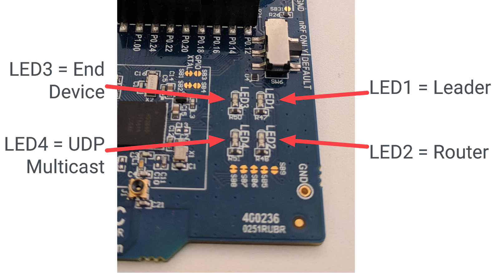
在我们的应用中,我们希望根据设备角色点亮不同的 LED。我们来跟踪以下角色:领导者、路由器、终端设备。我们可以按如下方式将它们分配给 LED:
- LED1 = Leader
- LED2 = 路由器
- LED3 = 终端设备
为了实现此功能,应用需要知道设备角色何时发生了变化,以及如何开启正确的 LED 来做出响应。我们将使用 OpenThread 实例进行第一部分,并使用 GPIO 平台抽象进行第二部分。
在首选文本编辑器中打开 ./openthread/examples/apps/cli/main.c 文件。
./openthread/examples/apps/cli/main.c
操作:添加了头文件包含项。
在 main.c 文件的包含部分中,添加角色更改功能所需的 API 头文件。
#include <openthread/instance.h>
#include <openthread/thread.h>
#include <openthread/thread_ftd.h>
操作:为 OpenThread 实例状态更改添加处理程序函数声明。
将此声明添加到 main.c 中,放在头文件包含内容之后,且位于任何 #if 语句之前。此函数将在主应用之后定义。
void handleNetifStateChanged(uint32_t aFlags, void *aContext);
操作:为状态更改处理函数添加回调注册。
在 main.c 中,将此函数添加到 main() 函数中的 otAppCliInit 调用之后。此回调注册会告知 OpenThread,每当 OpenThread 实例状态发生变化时,都调用 handleNetifStateChange 函数。
/* Register Thread state change handler */
otSetStateChangedCallback(instance, handleNetifStateChanged, instance);
操作:添加状态更改实现。
在 main.c 中,在 main() 函数之后,实现 handleNetifStateChanged 函数。此函数会检查 OpenThread 实例的 OT_CHANGED_THREAD_ROLE 标志,如果该标志已更改,则根据需要打开/关闭 LED。
void handleNetifStateChanged(uint32_t aFlags, void *aContext)
{
   if ((aFlags & OT_CHANGED_THREAD_ROLE) != 0)
   {
       otDeviceRole changedRole = otThreadGetDeviceRole(aContext);

       switch (changedRole)
       {
       case OT_DEVICE_ROLE_LEADER:
           otSysLedSet(1, true);
           otSysLedSet(2, false);
           otSysLedSet(3, false);
           break;

       case OT_DEVICE_ROLE_ROUTER:
           otSysLedSet(1, false);
           otSysLedSet(2, true);
           otSysLedSet(3, false);
           break;

       case OT_DEVICE_ROLE_CHILD:
           otSysLedSet(1, false);
           otSysLedSet(2, false);
           otSysLedSet(3, true);
           break;

       case OT_DEVICE_ROLE_DETACHED:
       case OT_DEVICE_ROLE_DISABLED:
           /* Clear LED4 if Thread is not enabled. */
           otSysLedSet(4, false);
           break;
        }
    }
}
7. API:使用多播打开 LED
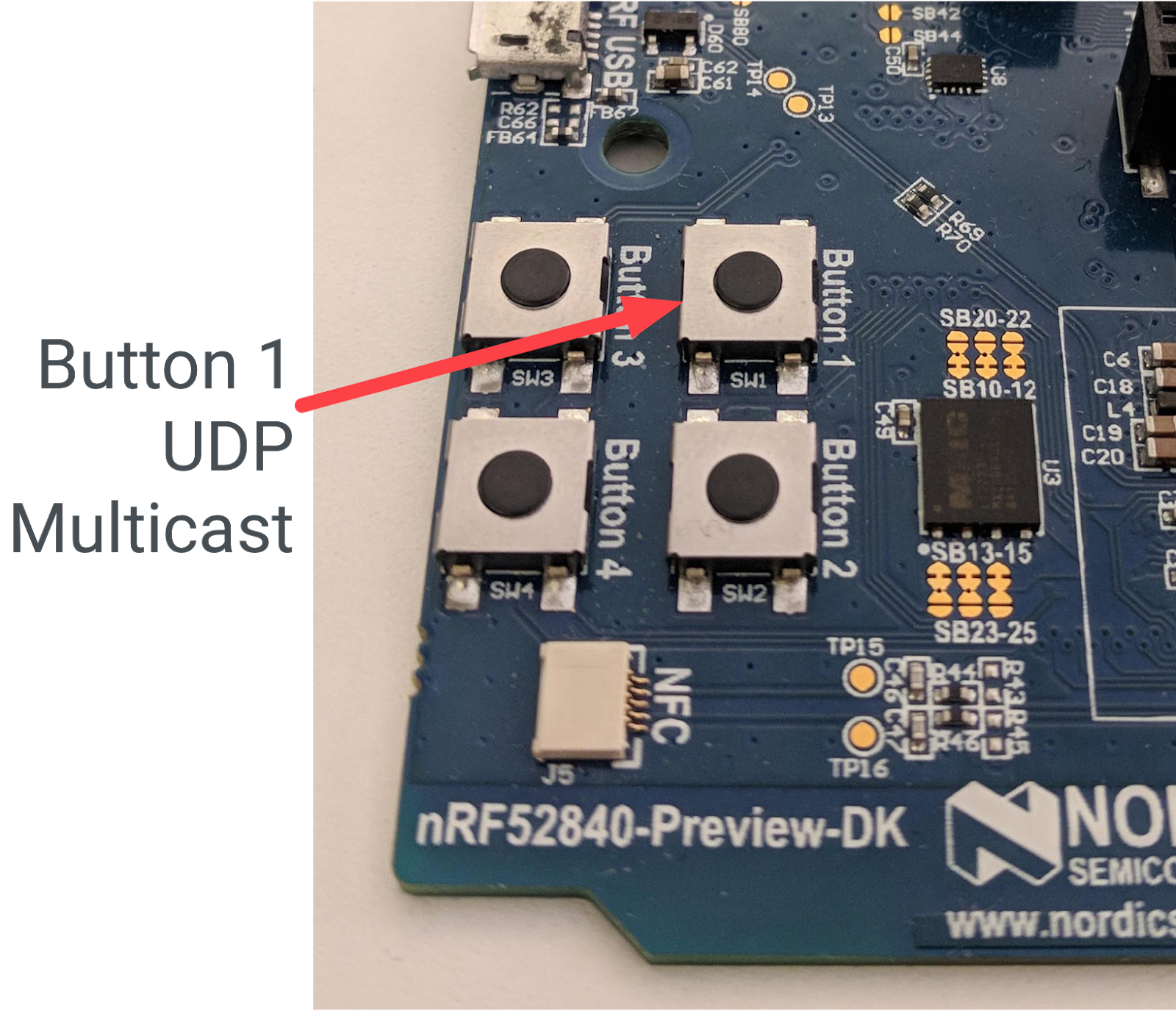
在我们的应用中,我们还希望在某个开发板上按下 Button1 时,向网络中的所有其他设备发送 UDP 消息。为了确认消息已收到,我们会切换其他板上的 LED4 以进行响应。
如需启用此功能,应用需要:
- 在启动时初始化 UDP 连接
- 能够向网格本地多播地址发送 UDP 消息
- 处理传入的 UDP 消息
- 响应传入的 UDP 消息时切换 LED4
在首选文本编辑器中打开 ./openthread/examples/apps/cli/main.c 文件。
./openthread/examples/apps/cli/main.c
操作:添加了头文件包含项。
在 main.c 文件顶部的包含部分中,添加多播 UDP 功能所需的 API 头文件。
#include <string.h>

#include <openthread/message.h>
#include <openthread/udp.h>

#include "utils/code_utils.h"
code_utils.h 标头用于 otEXPECT 和 otEXPECT_ACTION 宏,这些宏用于验证运行时条件并妥善处理错误。
操作:添加定义和常量:
在 main.c 文件中,在 include 部分之后和任何 #if 语句之前,添加特定于 UDP 的常量和定义:
#define UDP_PORT 1212

static const char UDP_DEST_ADDR[] = "ff03::1";
static const char UDP_PAYLOAD[]   = "Hello OpenThread World!";
ff03::1 是网状本地多播地址。发送到此地址的任何消息都将发送到网络中的所有 Full Thread 设备。如需详细了解 OpenThread 中的多播支持,请参阅 openthread.io 上的多播。
操作:添加函数声明。
在 main.c 文件中,在 otTaskletsSignalPending 定义之后和 main() 函数之前,添加特定于 UDP 的函数,以及一个表示 UDP 套接字的静态变量:
static void initUdp(otInstance *aInstance);
static void sendUdp(otInstance *aInstance);

static void handleButtonInterrupt(otInstance *aInstance);

void handleUdpReceive(void *aContext, otMessage *aMessage,
                      const otMessageInfo *aMessageInfo);

static otUdpSocket sUdpSocket;
操作:添加调用以初始化 GPIO LED 和按钮。
在 main.c 中,将这些函数调用添加到 main() 函数中的 otSetStateChangedCallback 调用之后。这些函数会初始化 GPIO 和 GPIOTE 引脚,并设置一个按钮处理程序来处理按钮按下事件。
/* init GPIO LEDs and button */
otSysLedInit();
otSysButtonInit(handleButtonInterrupt);
操作:添加 UDP 初始化调用。
在 main.c 中,将以下函数添加到您刚刚添加的 otSysButtonInit 调用之后的 main() 函数中:
initUdp(instance);
此调用可确保在应用启动时初始化 UDP 套接字。如果没有此权限,设备将无法发送或接收 UDP 消息。
操作:添加了用于处理 GPIO 按钮事件的调用。
在 main.c 中,将此函数调用添加到 main() 函数中的 otSysProcessDrivers 调用之后,在 while 循环中。此函数在 gpio.c 中声明,用于检查按钮是否被按下,如果被按下,则调用在上一步中设置的处理程序 (handleButtonInterrupt)。
otSysButtonProcess(instance);
操作:实现按钮中断处理程序。
在 main.c 中,在您在上一步中添加的 handleNetifStateChanged 函数后面,添加 handleButtonInterrupt 函数的实现:
/**
 * Function to handle button push event
 */
void handleButtonInterrupt(otInstance *aInstance)
{
    sendUdp(aInstance);
}
操作:实现 UDP 初始化。
在 main.c 中,在您刚刚添加的 handleButtonInterrupt 函数后面添加 initUdp 函数的实现:
/**
 * Initialize UDP socket
 */
void initUdp(otInstance *aInstance)
{
    otSockAddr  listenSockAddr;

    memset(&sUdpSocket, 0, sizeof(sUdpSocket));
    memset(&listenSockAddr, 0, sizeof(listenSockAddr));

    listenSockAddr.mPort    = UDP_PORT;

    otUdpOpen(aInstance, &sUdpSocket, handleUdpReceive, aInstance);
    otUdpBind(aInstance, &sUdpSocket, &listenSockAddr, OT_NETIF_THREAD);
}
UDP_PORT 是您之前定义的端口 (1212)。otUdpOpen 函数会打开套接字,并注册一个回调函数 (handleUdpReceive),以便在收到 UDP 消息时调用该函数。otUdpBind 通过传递 OT_NETIF_THREAD 将套接字绑定到 Thread 网络接口。如需了解其他网络接口选项,请参阅 UDP API 参考文档中的 otNetifIdentifier 枚举。
操作:实现 UDP 消息传递。
在 main.c 中,在您刚刚添加的 initUdp 函数后面添加 sendUdp 函数的实现:
/**
 * Send a UDP datagram
 */
void sendUdp(otInstance *aInstance)
{
    otError       error = OT_ERROR_NONE;
    otMessage *   message;
    otMessageInfo messageInfo;
    otIp6Address  destinationAddr;

    memset(&messageInfo, 0, sizeof(messageInfo));

    otIp6AddressFromString(UDP_DEST_ADDR, &destinationAddr);
    messageInfo.mPeerAddr    = destinationAddr;
    messageInfo.mPeerPort    = UDP_PORT;

    message = otUdpNewMessage(aInstance, NULL);
    otEXPECT_ACTION(message != NULL, error = OT_ERROR_NO_BUFS);

    error = otMessageAppend(message, UDP_PAYLOAD, sizeof(UDP_PAYLOAD));
    otEXPECT(error == OT_ERROR_NONE);

    error = otUdpSend(aInstance, &sUdpSocket, message, &messageInfo);

 exit:
    if (error != OT_ERROR_NONE && message != NULL)
    {
        otMessageFree(message);
    }
}
请注意 otEXPECT 和 otEXPECT_ACTION 宏。这些代码可确保 UDP 消息在缓冲区中有效且分配正确,否则,该函数会跳转到 exit 块,释放缓冲区,从而妥善处理错误。
如需详细了解用于初始化 UDP 的函数,请参阅 openthread.io 上的 IPv6 和 UDP 参考文档。
操作:实现 UDP 消息处理。
在 main.c 中,在您刚刚添加的 sendUdp 函数后面添加 handleUdpReceive 函数的实现。此函数只是切换 LED4。
/**
 * Function to handle UDP datagrams received on the listening socket
 */
void handleUdpReceive(void *aContext, otMessage *aMessage,
                      const otMessageInfo *aMessageInfo)
{
    OT_UNUSED_VARIABLE(aContext);
    OT_UNUSED_VARIABLE(aMessage);
    OT_UNUSED_VARIABLE(aMessageInfo);

    otSysLedToggle(4);
}
8. API:配置 Thread 网络
为了便于演示,我们希望设备在开机后立即启动 Thread 并加入网络。为此,我们将使用 otOperationalDataset 结构。此结构包含将 Thread 网络凭据传输到设备所需的所有参数。
使用此结构会替换 OpenThread 中内置的网络默认值,从而提高应用的安全性,并将网络中的 Thread 节点限制为仅运行该应用的节点。
再次在首选文本编辑器中打开 ./openthread/examples/apps/cli/main.c 文件。
./openthread/examples/apps/cli/main.c
操作:添加了标头 include。
在 main.c 文件顶部的“includes”部分中,添加配置 Thread 网络所需的 API 头文件:
#include <openthread/dataset_ftd.h>
操作:添加用于设置网络配置的函数声明。
将此声明添加到 main.c 中,放在头文件包含内容之后,且位于任何 #if 语句之前。此函数将在主应用函数之后定义。
static void setNetworkConfiguration(otInstance *aInstance);
操作:添加网络配置调用。
在 main.c 中,将此函数调用添加到 main() 函数中的 otSetStateChangedCallback 调用之后。此函数用于配置 Thread 网络数据集。
/* Override default network credentials */
setNetworkConfiguration(instance);
操作:添加调用以启用 Thread 网络接口和堆栈。
在 main.c 中,将这些函数调用添加到 main() 函数中的 otSysButtonInit 调用之后。
/* Start the Thread network interface (CLI cmd > ifconfig up) */
otIp6SetEnabled(instance, true);

/* Start the Thread stack (CLI cmd > thread start) */
otThreadSetEnabled(instance, true);
操作:实现 Thread 网络配置。
在 main.c 中,在 main() 函数后面添加 setNetworkConfiguration 函数的实现:
/**
 * Override default network settings, such as panid, so the devices can join a
 network
 */
void setNetworkConfiguration(otInstance *aInstance)
{
    static char          aNetworkName[] = "OTCodelab";
    otOperationalDataset aDataset;

    memset(&aDataset, 0, sizeof(otOperationalDataset));

    /*
     * Fields that can be configured in otOperationDataset to override defaults:
     *     Network Name, Mesh Local Prefix, Extended PAN ID, PAN ID, Delay Timer,
     *     Channel, Channel Mask Page 0, Network Key, PSKc, Security Policy
     */
    aDataset.mActiveTimestamp.mSeconds             = 1;
    aDataset.mActiveTimestamp.mTicks               = 0;
    aDataset.mActiveTimestamp.mAuthoritative       = false;
    aDataset.mComponents.mIsActiveTimestampPresent = true;

    /* Set Channel to 15 */
    aDataset.mChannel                      = 15;
    aDataset.mComponents.mIsChannelPresent = true;

    /* Set Pan ID to 2222 */
    aDataset.mPanId                      = (otPanId)0x2222;
    aDataset.mComponents.mIsPanIdPresent = true;

    /* Set Extended Pan ID to C0DE1AB5C0DE1AB5 */
    uint8_t extPanId[OT_EXT_PAN_ID_SIZE] = {0xC0, 0xDE, 0x1A, 0xB5, 0xC0, 0xDE, 0x1A, 0xB5};
    memcpy(aDataset.mExtendedPanId.m8, extPanId, sizeof(aDataset.mExtendedPanId));
    aDataset.mComponents.mIsExtendedPanIdPresent = true;

    /* Set network key to 1234C0DE1AB51234C0DE1AB51234C0DE */
    uint8_t key[OT_NETWORK_KEY_SIZE] = {0x12, 0x34, 0xC0, 0xDE, 0x1A, 0xB5, 0x12, 0x34, 0xC0, 0xDE, 0x1A, 0xB5, 0x12, 0x34, 0xC0, 0xDE};
    memcpy(aDataset.mNetworkKey.m8, key, sizeof(aDataset.mNetworkKey));
    aDataset.mComponents.mIsNetworkKeyPresent = true;

    /* Set Network Name to OTCodelab */
    size_t length = strlen(aNetworkName);
    assert(length <= OT_NETWORK_NAME_MAX_SIZE);
    memcpy(aDataset.mNetworkName.m8, aNetworkName, length);
    aDataset.mComponents.mIsNetworkNamePresent = true;

    otDatasetSetActive(aInstance, &aDataset);
    /* Set the router selection jitter to override the 2 minute default.
       CLI cmd > routerselectionjitter 20
       Warning: For demo purposes only - not to be used in a real product */
    uint8_t jitterValue = 20;
    otThreadSetRouterSelectionJitter(aInstance, jitterValue);
}
如函数中所详述,我们在此应用中使用的 Thread 网络参数如下:
- 渠道 = 15
- PAN ID = 0x2222
- 扩展的 PAN ID = C0DE1AB5C0DE1AB5
- 广告资源网密钥 = 1234C0DE1AB51234C0DE1AB51234C0DE
- 网络名称 = OTCodelab
此外,我们还在此处减少了路由器选择抖动,以便设备更快地更改角色以用于演示。请注意,只有当节点是 FTD(完整 Thread 设备)时,才会执行此操作。我们将在下一步中详细介绍这一点。
9. API:受限函数
OpenThread 的某些 API 会修改仅应出于演示或测试目的而修改的设置。这些 API 不应在正式版部署中使用 OpenThread 的应用中使用。
例如,otThreadSetRouterSelectionJitter 函数用于调整终端设备升级为路由器的所需时间(以秒为单位)。根据 Thread 规范,此值的默认值为 120。为了便于在此 Codelab 中使用,我们将此值更改为 20,这样您就不必等待很长时间才能让 Thread 节点更改角色。
注意:MTD 设备不会成为路由器,并且 MTD build 中不包含对 otThreadSetRouterSelectionJitter 等功能的支持。稍后,我们需要指定 CMake 选项 -DOT_MTD=OFF,否则会遇到 build 失败。
您可以通过查看 otThreadSetRouterSelectionJitter 函数定义来确认这一点,该定义包含在 OPENTHREAD_FTD 的预处理器指令中:
./openthread/src/core/api/thread_ftd_api.cpp
#if OPENTHREAD_FTD

#include <openthread/thread_ftd.h>

...

void otThreadSetRouterSelectionJitter(otInstance *aInstance, uint8_t aRouterJitter)
{
    Instance &instance = *static_cast<Instance *>(aInstance);

    instance.GetThreadNetif().GetMle().SetRouterSelectionJitter(aRouterJitter);
}

...

#endif // OPENTHREAD_FTD
10. CMake 更新
在构建应用之前,您需要对三个 CMake 文件进行一些小更新。构建系统会使用这些文件来编译和关联您的应用。
./third_party/NordicSemiconductor/CMakeLists.txt
现在,向 NordicSemiconductor CMakeLists.txt 添加一些标志,以确保在应用中定义了 GPIO 函数。
操作:向 CMakeLists.txt 文件添加标志。
在首选文本编辑器中打开 ./third_party/NordicSemiconductor/CMakeLists.txt,然后在 COMMON_FLAG 部分中添加以下代码行。
...
set(COMMON_FLAG
    -DSPIS_ENABLED=1
    -DSPIS0_ENABLED=1
    -DNRFX_SPIS_ENABLED=1
    -DNRFX_SPIS0_ENABLED=1
    ...

    # Defined in ./third_party/NordicSemiconductor/nrfx/templates/nRF52840/nrfx_config.h
    -DGPIOTE_ENABLED=1
    -DGPIOTE_CONFIG_IRQ_PRIORITY=7
    -DGPIOTE_CONFIG_NUM_OF_LOW_POWER_EVENTS=1
)

...
./src/CMakeLists.txt
修改 ./src/CMakeLists.txt 文件以添加新的 gpio.c 源文件:
操作:将 GPIO 源添加到 ./src/CMakeLists.txt 文件中。
在首选文本编辑器中打开 ./src/CMakeLists.txt,然后将该文件添加到 NRF_COMM_SOURCES 部分。
...

set(NRF_COMM_SOURCES
  ...
  src/gpio.c
  ...
)

...
./third_party/NordicSemiconductor/CMakeLists.txt
最后,将 nrfx_gpiote.c 驱动程序文件添加到 NordicSemiconductor CMakeLists.txt 文件,以便将其包含在 Nordic 驱动程序的库 build 中。
操作:将 GPIO 驱动程序添加到 NordicSemiconductor CMakeLists.txt 文件。
在首选文本编辑器中打开 ./third_party/NordicSemiconductor/CMakeLists.txt,然后将该文件添加到 COMMON_SOURCES 部分。
...

set(COMMON_SOURCES
  ...
  nrfx/drivers/src/nrfx_gpiote.c
  ...
)
...
11. 设置设备
完成所有代码更新后,您就可以构建应用并将其刷写到所有三个 Nordic nRF52840 开发板了。每台设备都将充当完整的 Thread 设备 (FTD)。
构建 OpenThread
为 nRF52840 平台构建 OpenThread FTD 二进制文件。
$ cd ~/ot-nrf528xx
$ ./script/build nrf52840 UART_trans -DOT_MTD=OFF -DOT_APP_RCP=OFF -DOT_RCP=OFF
前往包含 OpenThread FTD CLI 二进制文件的目录,然后使用 ARM 嵌入式工具链将其转换为十六进制格式:
$ cd build/bin
$ arm-none-eabi-objcopy -O ihex ot-cli-ftd ot-cli-ftd.hex
刷写板
将 ot-cli-ftd.hex 文件刷写到每个 nRF52840 板上。
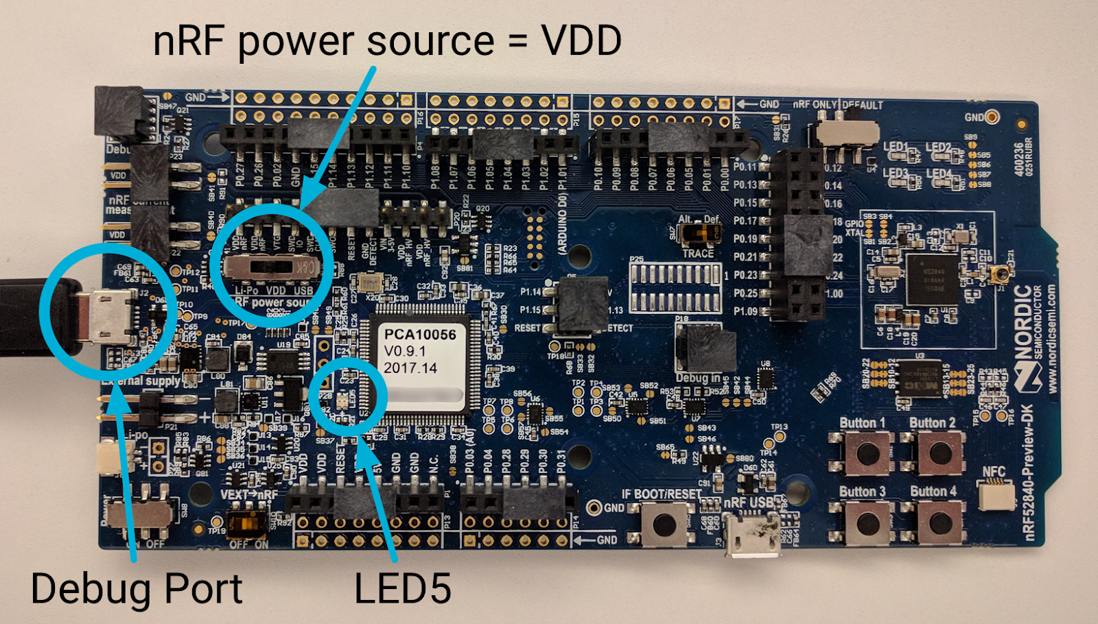
将 USB 线缆连接到 nRF52840 板上外部电源引脚旁边的 Micro-USB 调试端口,然后将其插入 Linux 机器。设置正确后,LED5 会亮起。
与之前一样,记下 nRF52840 板的序列号:
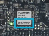
前往 nRFx 命令行工具的位置,然后使用 nRF52840 板的序列号将 OpenThread CLI FTD HEX 文件刷写到该板上:
$ cd ~/nrfjprog
$ ./nrfjprog -f nrf52 -s 683704924 --verify --chiperase --program \
       ~/openthread/output/nrf52840/bin/ot-cli-ftd.hex --reset
在刷写期间,LED5 会短暂关闭。成功后,系统会生成以下输出:
Parsing hex file.
Erasing user available code and UICR flash areas.
Applying system reset.
Checking that the area to write is not protected.
Programing device.
Applying system reset.
Run.
针对其他两个板重复执行此“刷写板”步骤。每块板卡都应以相同的方式连接到 Linux 机器,并且刷写命令相同,只是板卡的序列号不同。请务必在
nrfjprog 刷写命令。
如果成功,每个板上的 LED1、LED2 或 LED3 将亮起。您甚至可能会看到,在闪烁后不久,亮起的 LED 从 3 变为 2(或从 2 变为 1)(设备角色更改功能)。
12. 应用功能
现在,所有三个 nRF52840 板都应已通电并运行我们的 OpenThread 应用。如前文所述,此应用具有两项主要功能。
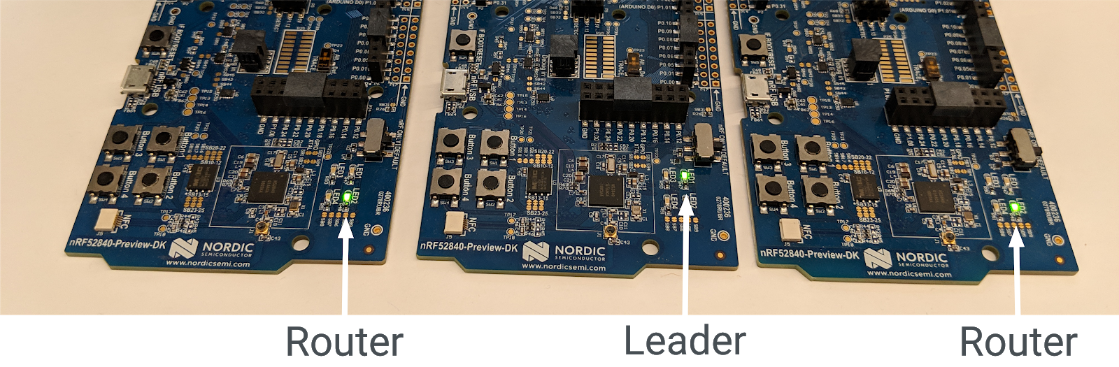
设备角色指示器
每个板上的亮起 LED 反映了 Thread 节点的当前角色:
- LED1 = Leader
- LED2 = 路由器
- LED3 = 终端设备
随着角色的变化,点亮的 LED 也会随之变化。您应该会在每个设备启动后的 20 秒内,在一两个板上看到这些更改。
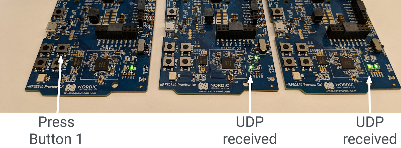
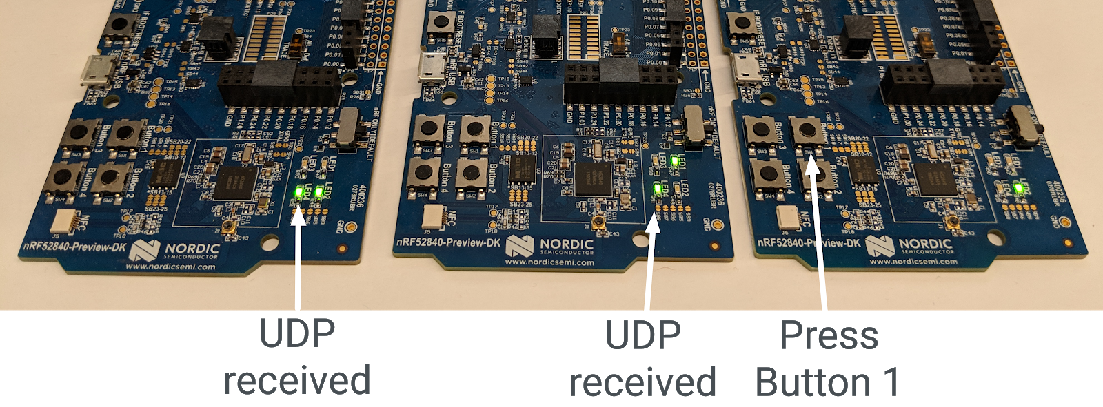
UDP 多播
当在开发板上按下 Button1 时,系统会向网格本地多播地址发送 UDP 消息,该地址包含 Thread 网络中的所有其他节点。收到此消息后,所有其他板上的 LED4 会切换为开启或关闭状态。在收到另一条 UDP 消息之前,每个板上的 LED4 都会保持开启或关闭状态。
13. 演示:观察设备角色变化
您刷写的设备是一种称为“符合路由器条件的终端设备 (REED)”的特定类型的完整 Thread 设备 (FTD)。这意味着它们既可以充当路由器,也可以充当终端设备,并且可以从终端设备升级为路由器。
Thread 最多可支持 32 个路由器,但会尽量将路由器数量保持在 16 到 23 之间。如果 REED 作为终端设备连接,且路由器数量低于 16,则会自动升级为路由器。此更改应在您在应用中将 otThreadSetRouterSelectionJitter 值设置到的秒数(20 秒)内随机发生。
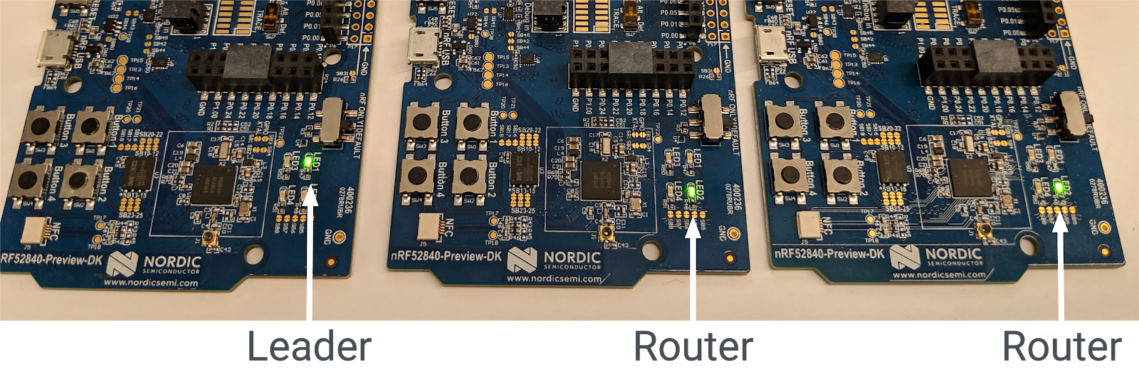
每个 Thread 网络还有一个 Leader,它是一个负责管理 Thread 网络中一组路由器的路由器。在所有设备都开启的情况下,20 秒后,其中一个设备应为 Leader(LED1 亮起),另外两个设备应为 Router(LED2 亮起)。
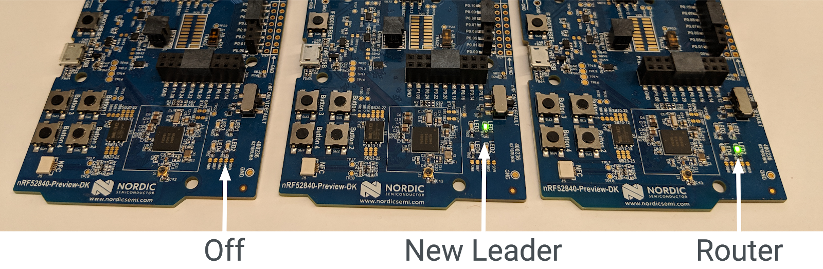
移除主管
如果从 Thread 网络中移除 Leader,则另一个路由器会自行升级为 Leader,以确保网络仍有 Leader。
使用电源开关关闭主板(LED1 指示灯亮起)。等待大约 20 秒。在剩余的两个板上,LED2(路由器)将关闭,LED1(主节点)将开启。此设备现在是 Thread 网络的 Leader。
重新开启原始排行榜。它应会自动重新加入 Thread 网络,成为终端设备(LED3 亮起)。在 20 秒内(路由器选择抖动),它会将自己提升为路由器(LED2 亮起)。
重置看板
关闭所有三块板,然后重新开启,并观察 LED。第一个启动的板应以领导者角色启动(LED1 亮起)- Thread 网络中的第一个路由器会自动成为领导者。
其他两个板最初以终端设备(LED3 亮起)的身份连接到网络,但应在 20 秒内将自己提升为路由器(LED2 亮起)。
网络分区
如果主板未获得足够的电量,或者它们之间的无线电连接较弱,Thread 网络可能会分成多个分区,并且您可能会看到多个设备显示为 Leader。
线程具有自我修复功能,因此分区最终应合并回具有一个 Leader 的单个分区。
14. 演示:发送 UDP 多播
如果继续完成上一个练习,则任何设备上的 LED4 都不应亮起。
选择任意板卡,然后按 Button1。Thread 网络中运行该应用的所有其他板上的 LED4 应切换其状态。如果继续上一个练习,则现在应处于开启状态。
再次按 Button1 即可选择同一板卡。所有其他板上的 LED4 应再次切换。
在其他开发板上按 Button1,观察其他开发板上的 LED4 如何切换。在 LED4 当前亮起的一个板上按下 Button1。LED4 在该主板上保持亮起,但在其他主板上会切换。
网络分区
如果您的板已分区,并且其中有多个 Leader,则多播消息的结果在不同板之间会有所不同。如果您在已分区(因此是分区 Thread 网络的唯一成员)的开发板上按 Button1,其他开发板上的 LED4 将不会亮起。如果发生这种情况,请重置板,理想情况下,它们会重新形成一个 Thread 网络,并且 UDP 消息传递应该可以正常工作。
15. 恭喜!
您已创建使用 OpenThread API 的应用!
您现在已了解:
- 如何对 Nordic nRF52840 开发板上的按钮和 LED 进行编程
- 如何使用常见的 OpenThread API 和
otInstance类 - 如何监控和响应 OpenThread 状态变化
- 如何向 Thread 网络中的所有设备发送 UDP 消息
- 如何修改 Makefile
后续步骤
在此 Codelab 的基础上,尝试做以下练习:
- 修改 GPIO 模块以使用 GPIO 引脚而不是板载 LED,并连接外部 RGB LED,这些 LED 会根据路由器的角色改变颜色
- 为其他示例平台添加了 GPIO 支持
- 使用 Router/Leader API 定位并 ping 单个设备,而不是使用多播在按下按钮时 ping 所有设备
- 使用 OpenThread 边界路由器将网状网络连接到互联网,并从 Thread 网络外部对它们进行多播,以点亮 LED
深入阅读
如需各种 OpenThread 资源,请访问 openthread.io 和 GitHub,其中包括:
- 支持的平台 - 了解支持 OpenThread 的所有平台
- 构建 OpenThread - 有关构建和配置 OpenThread 的更多详细信息
- Thread 入门指南 - 关于 Thread 概念的实用参考资料
参考: